Table of Contents
Advertisement
Advertisement
Table of Contents

Related Manuals for Elcontrol NanoVIP3


Summary of Contents for Elcontrol NanoVIP3
- Page 1 Man. NVIP3 – Rel. 1.3 EN (UK) USER MANUAL...
- Page 2 Man. NVIP3 – Rel 1.3 EN (UK) NanoVIP Congratulations on having chosen , a product based on Elcontrol's 50 years of experience in the control of power consumption. High technological content, careful material selection, and full compliance with the latest regulations, make this product the only one of its kind.
-
Page 3: Table Of Contents
Man. NVIP3 – Rel 1.3 EN (UK) TABLE OF CONTENTS Page Presentation Intended Use Safety Operators' Safety EC, RoHS & WEEE Declaration of Conformity Reference Standards Warranty Conditions Description & Connection to the Electrical System Power Supply USB Port Memory Card (uSD) Electrical Connection Schemes Start Up User Interface... - Page 4 Man. NVIP3 – Rel 1.3 EN (UK) 5.2.7 Snapshot Function 5.2.8 EN 50160 Menu 5.2.9 Alarm Menu 5.2.10 Transient Menu 5.2.10.1 Transient Setup 5.2.10.1.1 Input Selection 5.2.10.1.2 Voltage Threshold 5.2.10.1.3 Current Threshold 5.2.10.1.4 In Threshold 5.2.10.1.5 Transient Detecting Mode 5.2.10.2 Inrush Current Setup 5.2.10.2.1 Input Selection 5.2.10.2.2 Current Threshold...
-
Page 5: Presentation
Man. NVIP3 – Rel 1.3 EN (UK) 1 - PRESENTATION NanoVIP is a leading device equipped with new functions for measuring and monitoring power consumption and for advanced power and power quality analysis. This device can measure, display, process and transmit all the parameters of a system. - Page 6 Man. NVIP3 – Rel 1.3 EN (UK) • measure signals - including asymmetrical signals - for PWM controls on inverters; • identify the cause of problems resulting from low quality power (presence of harmonics, interruptions, overloads, dips, unbalance in voltage phases, etc.), which may bring about a production standstill, and which may affect or reduce the life cycle of equipment and systems;...
-
Page 7: Safety
The symbol shown here on the right - when found on the product or elsewhere - means that the user manual must be consulted 2.2 - EC, RoHS & WEEE Declaration of Conformity Manufacturer: ELCONTROL ENERGY NET S.r.l. Via Vizzano 44 40044 Sasso Marconi (BO) - Italy NanoVIP... -
Page 8: Reference Standards
Man. NVIP3 – Rel 1.3 EN (UK) 2.3 - Reference Standards Standard Title Description Int. Link General safety requirements for electrical Safety requirements for Identical to equipment intended professional, electrical equipment for EN 61010-1 industrial process, and educational use. measurement, control, and IEC 61010-1:2001-02 Electrical test and measurement, control, laboratory use. -
Page 9: Warranty Conditions
LIMITATION OF LIABILITY Except for the warranty, Elcontrol shall in no way be liable for any direct or indirect damage incurred by the purchaser, such as – but not limited to – material damage, damage for loss in profit and loss, damage to purchaser's documents, archives or data, damage for third party claims, and damage claimed by any party whatsoever, resulting from applications obtained by the purchaser for himself or third parties, with the help –... -
Page 10: Description & Connection To The Electrical System
600V CAT III, may be connected. The current inputs can be connected to the flexible current mini-clamps, which come with the instrument and are marked with special coloured rings, which correspond to the different phases. Alternatively, other Elcontrol Energy Net amperometric probes may be used, depending on the specific measurement requirements. -
Page 11: Usb Port
Man. NVIP3 – Rel 1.3 EN (UK) 3.2 - USB Port NanoVIP can be connected to a PC through the USB port and the cable supplied. This connection allows the user to download the MODBUS measurement registers using the PC Energy Studio Manager software. The USB communication may also allow easy upgrade of the firmware (internal software) of the instrument. -
Page 12: Electrical Connection Schemes
Man. NVIP3 – Rel 1.3 EN (UK) 3.4 - Electrical Connection Schemes Some examples of electrical connections are shown below (See Sect. 4.2.1.1). 3Φ Φ Φ Φ +N 3Φ Φ Φ Φ +N-BL The 4 current probe is optional (See Sect. - Page 13 Man. NVIP3 – Rel 1.3 EN (UK) 2Φ Φ Φ Φ The probe for measuring the neutral current is optional. 1Φ Φ Φ Φ - 13 -...
- Page 14 Man. NVIP3 – Rel 1.3 EN (UK) Dispersion Measurement I (can be combined with the previous schemes) LMA clamp is optional (See Sect. 9 – Accessories) Example of connection on inverter DC clamp and additional voltage cables are optional - 14 -...
-
Page 15: Start Up
Man. NVIP3 – Rel 1.3 EN (UK) 4 - START-UP Before using NanoVIP the correct configuration must be done, depending on the type of installation and system to which it will be connected. Make sure the electrical cabinet is off before connecting the instrument. -
Page 16: Bottom Bar
Man. NVIP3 – Rel 1.3 EN (UK) NOTE: based on the type of menu, the area of related parameters and/or the bottom bar may not be displayed. 4.1.1.1 - Bottom Bar This area displays information regarding the status of the instrument, such as: 1) Battery level 4) Type of electrical connection 2) MicroSD card... -
Page 17: Programming & Setup
Man. NVIP3 – Rel 1.3 EN (UK) FUNCTION Press Once Press and Hold for 3 seconds Switch the instrument ON and OFF Access to VOLTAGES Menu Access to COUNTERS Menu ϕ ϕ ϕ ϕ Access to CURRENTS Menu Access to HARMONICS - THD - C Menu Access to POWER Menu Access to WAVEFORMS Menu... - Page 18 Flowchart of Setup Menu Man. NVIP3 – Rel 1.3 EN (UK) AMPEROMETRIC MINIMUM, MAXIMUM & CONNECTIONS SETUP (4.2.1) SENSORS SETUP (4.2.2) AVERAGE SETUP (4.2.3) COUNTERS SETUP (4.2.4) (3”) CLOCK SETUP (4.2.7) BOTTOM BAR SETUP (4.2.8) LANGUAGE SETUP LCD SETUP (4.2.6) (4.2.5) TARIFFS SETUP (4.2.9) EN50160 SETUP (4.2.10)
-
Page 19: Connections Setup
Man. NVIP3 – Rel 1.3 EN (UK) 4.2.1 - Connections Setup This menu allows the user to: Set the type of electrical network to which the instrument is ● connected (Sect. 4.2.1.1). Set the type of voltage and voltage ratio for phases L1, L2, and L3 ●... -
Page 20: Current Probes Setup
Man. NVIP3 – Rel 1.3 EN (UK) • Voltage phase sequence • Threshold of the measured PF which allows for a correct analysis (if the PF is lower than the value indicated, the check cannot provide valid information) • Check of the correspondence between voltage and current of each phaseand possible error message: Ok = Connection is correct Invert CT = Invert the direction of the current clamp... -
Page 21: Reset Of Minimum & Maximum Values
Man. NVIP3 – Rel 1.3 EN (UK) 4.2.3.3 - Reset of Minimum & Maximum Values To reset the minimum and maximum instant values, place the cursor on RESET MIN MAX and select YES. 4.2.4 - Counters Reset To reset the counters of both absorbed and generated power, place the cursor on COUNTERS RESET and select YES. -
Page 22: Display Orientation Setup
Man. NVIP3 – Rel 1.3 EN (UK) Obviously, with time, LCD efficiency will depend on the number of hours of operation and the level of brightness selected (Sect. 4.2.6.3). Therefore, unless strictly necessary, we advise against the level of brightness being higher than 70 and keeping the backlight ALWAYS ON. -
Page 23: Tariff Setup
Man. NVIP3 – Rel 1.3 EN (UK) 4.2.9 - Tariffs Setup Choose the tariff band to be set by selecting it with the cursor. Then press to access the relevant configuration and reset the submenu (Sect. 4.2.9.1). This function resets the measurements previously performed (for all ●... -
Page 24: En 50160 Setup & Reset
Man. NVIP3 – Rel 1.3 EN (UK) 4.2.10 - EN 50160 Setup & Reset As described in Standard EN 50160, the phenomenon “voltage disturbances” (swells, dips, interruptions, etc.) does not feature standard values by means of which power quality can be evaluated. Therefore, it is the user's responsibility to evaluate whether the voltage disturbances of the system are actually harmful or if they can be disregarded, based on the type of installation, production, connected instrument, etc. -
Page 25: Alarm Setup & Reset
Man. NVIP3 – Rel 1.3 EN (UK) 4.2.12 - Alarm Setup & Reset Two alarms can be set and configured with NanoVIP Place the cursor either alarm and press to access the ● relevant configuration submenu. ● ● ● ● ●... -
Page 26: Instrument Use & Consultation
Man. NVIP3 – Rel 1.3 EN (UK) 5 - INSTRUMENT USE & CONSULTATION The NanoVIP keypad allows the user to access all the menus of the instrument directly, thanks to its practical function keys. Press the desired key to access the relevant menu. Use the arrow keys to scroll through the different pages of a menu. - Page 27 Man. NVIP3 – Rel 1.3 EN (UK) Flowchart of MEASUREMENT MENUS in THREE-PHASE WITH NEUTRAL connection. VOLTAGES MENU (Sect. 5.2.1). AUX CH. (V) CURRENTS MENU (Sect. 5.2.2). AUX CH (I). POWER MENU (Sect. 5.2.3). AUX CH. (P) x3” COUNTERS MENU (Sect. 5.2.4). AUX CH.
- Page 28 Man. NVIP3 – Rel 1.3 EN (UK) x3” WAVEFORMS MENU (Sect. 5.2.6). AUX CH. (WAVEFORMS) AUX CHANNEL MENU VOLTAGES MENU CURRENTS MENU POWER MENU x3” COUNTERS MENU x3” x3” HARMONICS MENU x3” WAVEFORMS MENU x3” EN 50160 MENU (Sect. 5.2.8). - 28 -...
- Page 29 Man. NVIP3 – Rel 1.3 EN (UK) x3” ALARMS MENU (Sect. 5.2.9). TRANSIENTS MENU (Sect. 5.2.10) x3” x3” MEASUREMENT CAMPAIGNS (Sect. 5.2.11) - 29 -...
- Page 30 Man. NVIP3 – Rel 1.3 EN (UK) Flowchart of MEASUREMENT MENUS in SINGLE-PHASE connection. VOLTAGES MENU (Sect. 5.3.1). CURRENTS MENU (Sect. 5.3.2). POWER MENU (Sect. 5.3.3). x3” COUNTERS MENU (Sect. 5.3.4). x3” HARMONICS MENU (Sect. 5.3.5). - 30 -...
- Page 31 Man. NVIP3 – Rel 1.3 EN (UK) x3” WAVEFORMS MENU (Sect. 5.3.6). x3” EN 50160 MENU (Sect. 5.2.8). x3” ALARMS MENU (Sect. 5.2.9). TRANSIENTS MENU (Sect. 5.2.10) x3” x3” MEASUREMENT CAMPAIGNS (Sect. 5.2.11) - 31 -...
-
Page 32: Three-Phase Or Two-Phase Connection Menus
Man. NVIP3 – Rel 1.3 EN (UK) 5.2 - Three-phase or Two-phase Connection Menu When switching on the instrument or exiting the Setup Menu, NanoVIP displays the first page of the Voltages Menu. As shown in the flowcharts, the menus have a loop-type structure, i.e. when the end of the last page is reached, the menu automatically returns to the first page. -
Page 33: Currents Menu
Man. NVIP3 – Rel 1.3 EN (UK) Maximum instant voltage values (Values can be reset as described in Sect. 4.2.3.3) On any of the Voltages Menu pages, press to access the page containing all the information regarding auxiliary channel voltage. In the AUX Menu, the user can also access the other Auxiliary Channel Menus (Currents, Power, Counters, Harmonics, Waveforms) by selecting them with the relevant function keys. -
Page 34: Power Menu
Man. NVIP3 – Rel 1.3 EN (UK) Maximum instant current values in each phase (values can be reset as described in Sect. 4.2.3.3) Load peaks, i.e. the highest average current (calculated on the basis of the integration time set. Values can be reset as described in Sect. 4.2.3.2) On any of the Currents Menu pages, press to access the page containing all the information regarding the auxiliary channel current. - Page 35 Man. NVIP3 – Rel 1.3 EN (UK) PF values in each phase and in the three-phase (or two-phase) connection and the relevant type (Ind = Inductive load; Cap = Capacitive load) NOTE: the PF is always positive. As a norm, it is shown as a negative when active power is generated and a positive when absorbed.
-
Page 36: Counters Menu
Man. NVIP3 – Rel 1.3 EN (UK) Average power and PF (calculated on the basis of the integration time set. Values can be reset as described in Sect. 4.2.3) related to the auxiliary channel. Minimum instant values of power and PF (values can be reset as described in Sect. 4.2.3.3) related to the auxiliary channel. - Page 37 Man. NVIP3 – Rel 1.3 EN (UK) The counters of the apparent power (kVAh) in each phase and in the three- or two-phase connections. The counters of the active power generated (-kWh) in each phase and in three- or two- phase connections.
-
Page 38: Harmonics Menu
Man. NVIP3 – Rel 1.3 EN (UK) The kWh generated during the various time bands. The kVArh generated during the various time bands. The cost of the kWh absorbed during the various tariff bands, expressed in the currency selected in the Setup Menu (Sect. 4.2.9.1). The income expressed in the set currency unit (sect. - Page 39 Man. NVIP3 – Rel 1.3 EN (UK) The next page displays the THD% of the current of each phase and the three-phase (or two-phase) connection, as well as the THD% of the relevant phase voltages. ϕ This page displays the cos of the 3 phases with the relevant angles expressed in degrees (the negative sign indicates that current comes before voltage;...
-
Page 40: Consulting Harmonic Histograms
Man. NVIP3 – Rel 1.3 EN (UK) Harmonic histogram of neutral current. To select and scroll through single harmonics, see Sect. 5.2.5.1 On any of the Harmonics Menu pages, press to access two pages containing all the information regarding auxiliary channel harmonics. The first page displays the THD% of V and I. -
Page 41: Waveforms Menu
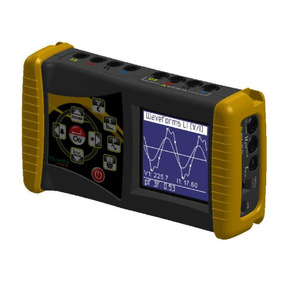
Man. NVIP3 – Rel 1.3 EN (UK) x3” 5.2.6 - Waveforms Menu This menu shows the real-time waveforms and the relevant system voltage and current values. NOTE: current tracing can be distinguished from voltage tracing by little ● square markers. Waveform amplitude is purely indicative and is automatically adjusted to screen size. -
Page 42: Snapshot Function
Man. NVIP3 – Rel 1.3 EN (UK) 5.2.7 - Snapshot Function During measurements, press the key to block all measurements immediately – not only those currently displayed. By doing so, the measurements will remain "frozen" on screen until the same key is pressed again. After blocking the measurements, all other menus can be scrolled through to check the status of the other parameters captured at the same time. -
Page 43: Alarm Menu
Man. NVIP3 – Rel 1.3 EN (UK) These pages display the last 5 swells recorded (if any occurred). NOTE: according to Standard EN50160, a "swell" is defined as an increase of one or more phase voltages above 110% of nominal V (See Setup, Sect. 4.2.10). However, a different threshold may be set by the user. -
Page 44: Transient Menu
Man. NVIP3 – Rel 1.3 EN (UK) 5.2.10.1 - Transients Setup This page allows the user to set the thresholds that the instrument will use to identify the transient event (i.e. the instant swell or overcurrent of peak). The following parameters must be set: •... -
Page 45: Inrush Current Setup
Man. NVIP3 – Rel 1.3 EN (UK) If NanoVIP detects a transient, the following information will be displayed: • Channel(s) in which the transient has occurred. • Transient waveform. • Relevant peak value. To scroll through the transients that occurred at the same time as the one being displayed (all the channels on which a transient has occurred are listed in the heading of the page), use the keys. -
Page 46: Manual Start
Man. NVIP3 – Rel 1.3 EN (UK) 5.2.10.2.5 - Manual Start If manual start is selected, the instrument will detect any current (without the threshold set acting as a trigger) occurring during the time period selected. At the end of the selected time period, the waveform detected will be displayed (Sect. -
Page 47: Storing Rate
Man. NVIP3 – Rel 1.3 EN (UK) 5.2.11.1.2 - Storing Rate This parameter indicates the rate at which NanoVIP stores the data. The following options are available: 1” - 5” - 30” - 1’ - 5’ - 15’. Obviously, from the choice of memorization frequency and duration of the campaign, will depend the MB employed by the campaign on uSD. -
Page 48: Single-Phase Connection Menu
Man. NVIP3 – Rel 1.3 EN (UK) 5.3 - Single-phase Connection Menu As already mentioned, if the single-phase connection is set, the instrument will automatically change the structure of the menus, eliminating the non-applicable items for this type of electrical connection, and grouping information in fewer pages. - Page 49 Man. NVIP3 – Rel 1.3 EN (UK) Average power and PF (calculated on the basis of the integration time set. Values can be reset as described in Sect. 4.3.3). Minimum instant values of power and PF (values can be reset as described in Sect. 4.2.3.3).
-
Page 50: Counters Menu (1Ph)
Man. NVIP3 – Rel 1.3 EN (UK) Minimum instant values of power and PF (values can be reset as described in Sect. 4.2.3.3) related to the auxiliary channel. Maximum instant values of power and PF (values can be reset as described in Sect. 4.2.3.3) related to the auxiliary channel. -
Page 51: Harmonics Menu (1Ph)
Man. NVIP3 – Rel 1.3 EN (UK) The kWh generated during the various time bands. The kVArh generated during the various time bands. The cost of the kWh absorbed during the various tariff bands, expressed in the currency selected in the Setup Menu (Sect. 4.2.9.1). The income expressed in the set currency unit (sect. - Page 52 Man. NVIP3 – Rel 1.3 EN (UK) K factor Harmonic histogram of current and voltage. On any of the Harmonics Menu pages, press to access two pages containing all the information regarding auxiliary channel harmonics. The first page displays the THD% of V and I.
-
Page 53: Waveforms Menu (1Ph)
Man. NVIP3 – Rel 1.3 EN (UK) x3” 5.3.6 - Waveforms Menu (1ph) This page displays the real-time waveforms and the relevant voltage and current RMS values. NOTE: current tracing can be distinguished from voltage tracing by little ● square markers. Waveform amplitude is purely indicative and is automatically adjusted to screen size. -
Page 54: Maintenance
If new calibration is required, the instrument can be sent to the manufacturer's in-house laboratory. If deemed appropriate, the user can also request that the manufacturer perform the accuracy check. NOTE: the in-house calibration laboratory of Elcontrol Energy Net is currently the only authorised calibration centre used. -
Page 55: Nanostudio Software
Man. NVIP3 – Rel 1.3 EN (UK) 7 - NANOSTUDIO SOFTWARE NANOSTUDIO Software is a simple and practical tool for analysing the measurement campaigns performed with NANOVIP NANOSTUDIO is compatible with WINDOWS XP, WINDOWS VISTA, and WINDOWS7. To install it, launch the file SETUP.EXE contained on the uSD card and follow the instructions provided. -
Page 56: Technical Specifications
4mm, 90° protected blade plug connector, and a crocodile clip with a 45mm opening (for sections up to 32mm) Currents Elcontrol Energy Net interchangeable amperometric sensors FUNCTIONS: V, I, P, Q, S, F, PF, THD(V)%, THD(I)%, cosϕ, ϕ, peaks, minimums, Traditional electrical analisys maximums, averages, max. - Page 57 Man. NVIP3 – Rel 1.3 EN (UK) Scales Direct measurement Phase-phase: 7-1000VAC 40-70Hz Phase-neutral: 5-600VAC 40-70Hz Aux: 5-1000VAC 40-70Hz 10-1400VDC Ratio: 1-60000 Measurement with VT Maximum value which can be displayed: 20MV Phase-phase: 1200VAC Permanent overload Phase-neutral: 700VAC Aux: 1200VAC 1700VDC Sensitivity 5VAC Phase-neutral, 7VAC Phase-phase...
- Page 58 Man. NVIP3 – Rel 1.3 EN (UK) Equipment); REFERENCE STANDARDS: Safety EN 61010-1 Electromagnetic Compatibility (EMC) EN 61326 EN 61326/A1 EN 61326/A2 EN 61326/A3 Temperature IEC 60068-2-1 (Operating temperature) IEC 60068-2-2 (Storing temperature) Vibrations IEC 60068-2-6 Humidity IEC 60068-2-30 (Humidity) Overload IEC 60947-1 The instrument changes the voltage and current scale automatically when the values of the signals detected...
-
Page 59: Accessories & Spare Parts
Man. NVIP3 – Rel 1.3 EN (UK) 9 - ACCESSORIES & SPARE PARTS NanoVIP KIT is composed by: n. 1 NanoVIP handheld energy analyser n. 1 battery pack n. 4 voltage cables (yellow, black, red, blue) with integrated alligator clips n. -
Page 60: Appendix 1 - Modbus Measurement Registers
Man. NVIP3 – Rel 1.3 EN (UK) Appendix 1 - MODBUS Measurement Registers Elcontrol standard MODBUS registers: 0001 V (3ph) Three-phase voltage (BCD mantissa) 0002 V (3 ph ) Three-phase voltage (exponent in binary format) 0003 A (3 ph ) - Page 61 Man. NVIP3 – Rel 1.3 EN (UK) 0073 Neutral current 0074 Neutral current 0075 A avg (L1) Average current L1 (average calculated according to integration time set - see 4.2.2) 0076 A avg (L1) Average current L1 0077 A avg (L2) Average current L2 0078 A avg (L2)
- Page 62 Man. NVIP3 – Rel 1.3 EN (UK) 0221 V2 h02 Harmonic No.2 voltage L2 0222 V2 h02 Harmonic No.2 voltage L2 0223 V3 h02 Harmonic No.2 voltage L3 0224 V3 h02 Harmonic No.2 voltage L3 ……. Consecutive addresses up to the 25th harmonic: H25 Harmonic 25 0357 V1 h25...
- Page 63 Man. NVIP3 – Rel 1.3 EN (UK) NEW NANOVIP REGISTERS 1001 V (3ph) Three-phase voltage (BCD mantissa) 1002 V (3 ph ) Three-phase voltage (exponent in binary format) 1003 A (3 ph ) Three-phase current 1004 A (3 ph ) Three-phase current 1005 kW (3 ph...
- Page 64 Man. NVIP3 – Rel 1.3 EN (UK) 1074 V max (L1) Maximum voltage L1 1075 V max (L2) Maximum voltage L2 1076 V max (L2) Maximum voltage L2 1077 V max (L3) Maximum voltage L3 1078 V max (L3) Maximum voltage L3 1079 A avg (L1) Average current L1...
- Page 65 Man. NVIP3 – Rel 1.3 EN (UK) 1149 kVArh cog Three-phase counter of generated reactive power 1150 kVAh (3 ph ) Three-phase apparent power counter 1151 kVAh (3 ph ) Three-phase apparent power counter 1152 kVAh (3 ph ) Three-phase apparent power counter 1153 kWh (L1 ) Three-phase active power counter L1...
- Page 66 Man. NVIP3 – Rel 1.3 EN (UK) 1224 kWh T1 Three-phase counter of generated active power (tariff T1 1225 kWh T2 Three-phase counter of generated active power (tariff T2 1226 kWh T2 Three-phase counter of generated active power (tariff T2 1227 kWh T2 Three-phase counter of generated active power (tariff T2...
- Page 67 Man. NVIP3 – Rel 1.3 EN (UK) Current Harmonics H01 (Fundamental) 1460 A1 h01 Harmonic No.1 current L1 1461 A1 h01 Harmonic No.1 current L1 1462 A2 h01 Harmonic No.1 current L2 1463 A2 h01 Harmonic No.1 current L2 1464 A3 h01 Harmonic No.1 current L3 1465...
- Page 68 Man. NVIP3 – Rel 1.3 EN (UK) 1861 Number of Interruptions 1862 Number of Dips 1863 Number of Dips 1864 Number of Swells 1865 Number of Swells See documentation on Elcontrol website in case of use and development of own software. - 68 -...
Need help?
Do you have a question about the NanoVIP3 and is the answer not in the manual?
Questions and answers