Table of Contents
Advertisement
Quick Links
Advertisement
Table of Contents

Related Manuals for Staufenbiel Aiolos HSF0314083


Summary of Contents for Staufenbiel Aiolos HSF0314083
- Page 1 Manual Aiolos HSF0314083 / HSF0314083E...
-
Page 2: Safety Precautions And Warnings
Do not use with incompatible compo- nents or alter this product in any way outside of the instructions provided by Gustav Staufenbiel GmbH. This manual contains instructions for safety, operation and maintenance. It is essential to read and follow all the instructions and warnings in the manual, prior to assembly, setup or use, in order to operate correctly and avoid damage or serious injury. -
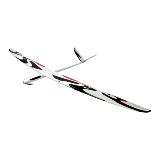
Page 3: Specifications
Manual Aiolos Specifications: R/C functions: • Span: 3180 mm • Aileron • Length: 1420 mm • Elevator • Wing area: 62,2 dm² • Rudder • Weight: 1700 g (dry) • Flaps • Airfoil: RG14spec (HS-001) • (Motor) - Page 4 Manual Aiolos The Fuselage Prepare for the first step two cable con- nectors from MPX and Servo and isolate them with heat shrink tube as shown on the left. Cable lenght: Male servo connector --> Flaps: 41cm Male servo connector --> Aileron: 90cm Female servo connector -->...
- Page 5 Manual Aiolos Due to the competetion design of the fuselage it could be possible depending on componets size to make some com- promises in the positions of the ESC and receiver. We recomend to extend all ESC cable and install the ESC under the wing joiner.
- Page 6 Manual Aiolos Drill a hole at the edge of the canopy frame. This hole will be used for tighten the servohorn. Position the servo exactly below the hole. Glue the servotray with thick epoxy. Drill a slot with a rotary cutter in the V-tail rudder.
- Page 7 Manual Aiolos Glue the aluminium rudder horn with UHU Endfest 300. Please take care that the glue is also in the opening for the rudder horn. Assembly the carbon rod. Cut them to 105cm (2x) . Glue a threaded bar in the carbon rod and a clevis with nut.
- Page 8 Manual Aiolos Adjust the carbon rod to the servo and fix it with Tesa outside of the fuselage. Fix an M2 threadet rod in the opposite end of the carbonrod and fix it to the end of the alumi- nium rudderhorn. Please take care that all grease is removed from the rod and glue it with Uhu End-...
- Page 9 Manual Aiolos Route the linkage through the fuselage and connect it to the second hole of servo horn. If needet adjust the lenght with turnig the clevis. Fasten the servohorn through the previous drilled hole. Prepare two notches in the fuselage for the alu- minium rudderhorn.
- Page 10 Manual Aiolos Drill two notches to the fuselage endcap and secure it with Tesa. The Giga-flaps will be actuatet with a piece of the Tesa tape. Prepare a Tesa stripe and fold 5mm width the glue side to the glue side. You will have now a piece of tape with a 5mm non gluing dou- ble tape layer part.
- Page 11 Manual Aiolos Glue hook and loop tape on the back of the lipo and in the fuselage. If you use high qualtity velcro no additional fasteners are required. As the last step for the fu- selage, install the motor, spinner and propeller. Please use again thread- lock.
-
Page 12: The Wing
Manual Aiolos The wing Start with shrinking the Aileron- and Flapservos with Heatshrink tube. Adjust all servos to neu- tral. Cut the servoarm till two holes left as shown. Glue the torsion pins with 5 min epoxy. Please note that the pins should protrude 8mm out of the wings. - Page 13 Manual Aiolos Route the cable harness in the wing. Adjust the the MPX con- nector to the connector in the fuselage and glue it in the wing. The aileron and flap lin- kage will be installed on top of the wing. Mark as shown the center of the wing cover scoop.
- Page 14 Manual Aiolos Drill a 3mm marking hole direkt in front of the trailing edge. Please note that the hole must be in one line to the servo- horn. Drill a 6x 17mm opening for the clevis in the top side of the wing. Use the hole from the previous step as a reference.
- Page 15 Manual Aiolos Depending on the hard- ware drill qualitity it could be better to drill the first hole (3mm) ver- tical and then change to the template. Glue the eybolts without the threadet inserts with UHU Endfest. For addi- tional stiffness it is re- commended to ad some glue on the inside of the rudder.
- Page 16 Manual Aiolos Connect the Servo to the cable harness and install the linkage. Use Tesa tape for fixing the servo cover on the bottom side of the wing that the servo is still ac- cessible. Glue the linkage scoop on the topside with epoxy.
- Page 17 Manual Aiolos The Giga-Flaps will be actuatet with a piece of the Tesa tape. Prepare a Tesa stripe and fold 5mm width the glue side to the glue side. You will have now a piece of tape with a 5mm non gluing dou- ble tape layer part.
-
Page 18: Center Of Gravity (Cg)
Manual Aiolos Center of gravity (C.G.): 105 mm behind the nose Control Throws: Flugphase Funktion Normal Thermik Speed Aileron U/D 20/12 mm, Butterfly: U 18 mm Elevator U 10 mm / D 8 mm Rudder L/R 12 mm Flaps Mix with Aileron: U/D 9/8 mm, D 5 mm U 4 mm Butterfly: D maximal... -
Page 19: Declaration Of Conformity
Manual Aiolos DECLARATION OF CONFORMITY EU Compliance Statement: Horizon Hobby, LLC hereby declares that this product is in compliance with the essential requirements and other relevant provisions of the EMC Directive. A copy of the EU Declaration of Conformity is available online at: http://www.horizonhobby.com/content/support-render-compliance.
Need help?
Do you have a question about the Aiolos HSF0314083 and is the answer not in the manual?
Questions and answers