Ursalink UR75 User Manual
Industrial cellular router
Hide thumbs
Also See for UR75:
- Quick start manual (18 pages) ,
- Quick start manual (18 pages) ,
- Quick start manual (18 pages)
Table of Contents
Advertisement
Quick Links
Advertisement
Table of Contents

Related Manuals for Ursalink UR75


Summary of Contents for Ursalink UR75
- Page 1 UR75 User Guide...
- Page 2 Ursalink UR75 Datasheet cellular router. Quick Installation guide for the Ursalink UR75 Ursalink UR75 Quick Start Guide series industrial cellular router. Declaration of Conformity UR75 is in conformity with the essential requirements and other relevant provisions of the CE, FCC, and RoHS.
- Page 3 UR75 User Guide For assistance, please contact Ursalink technical support: Email: support@ursalink.com Tel.: 86-592-5023060 Fax: 86-592-5023065 Revision History Date Doc Version Description Nov. 14, 2017 V.1.0.0 Initial version...
-
Page 4: Table Of Contents
UR75 User Guide Contents Chapter 1 Product Introduction..........................8 1.1 Overview..............................8 1.2 Advantages..............................8 1.3 Specifications............................10 1.4 Dimensions (mm)............................12 Chapter 2 Installation............................. 13 2.1 General Packing List..........................13 2.2 Product Overview............................. 14 2.3 LED Indicators............................14 2.5 PIN Definition............................15 2.6 Reset Button..............................16 2.7 SIM Card Installation.......................... - Page 5 UR75 User Guide 4.2.1.5 Cellular..........................40 4.2.1.7 Loopback..........................43 4.2.2 Firewall............................44 4.2.2.1 ACL............................44 4.2.2.2 DMZ.............................46 4.2.2.3 Port Mapping........................46 4.2.2.4 MAC Binding........................47 4.2.3 QoS..............................48 4.2.3.1 QoS (Download/Upload)....................48 4.2.4 DHCP...............................49 4.2.4.1 DHCP Server........................49 4.2.4.2 DHCP Relay......................... 51 4.2.5 DDNS.............................. 51 4.2.6 Link Failover...........................
- Page 6 UR75 User Guide 4.3.3.3 VACM...........................93 4.3.3.4 Trap............................. 94 4.3.3.5 MIB............................94 4.3.4 AAA.................................95 4.3.4.1 Radius..........................95 4.3.4.2 TACACS+..........................95 4.3.4.3 LDAP............................ 96 4.3.4.4 Authentication........................97 4.3.5 Device Management........................98 4.3.6 Events............................. 98 4.3.6.1 Events..........................98 4.3.6.2 Events Settings........................99 4.4 Industrial Interface..........................100 4.4.1 I/O..............................101 4.4.1.1 DI............................
- Page 7 UR75 User Guide 5.2 Common User Management........................123 5.3 System Time Management........................124 5.4 Backup and Restore Configuration......................126 5.5 Restore Factory Defaults........................127 5.5.1 Via Web Interface........................127 5.5.2 Via Hardware..........................128 5.6 Firmware Upgrade..........................129 5.7 Events Application Example........................131 5.8 Schedule Application Example.......................132...
-
Page 8: Chapter 1 Product Introduction
Adopting high-performance and low-power consumption industrial platform of 64-bit CPU and wireless module, the UR75 is capable of providing wire-speed network with a typical 2.9 W power consumption and ultra-small package to ensure the extremely safe and reliable connection to the wireless network. - Page 9 AAA (TACACS+, Radius, LDAP, local authentication) and multiple levels of user authority Easy Maintenance Ursalink Device Management Platform provides easy setup, mass configuration, and centralized management of remote devices The user-friendly web interface design and more than one option of upgrade help administrator to...
-
Page 10: Specifications
UR75 User Guide 1.3 Specifications Cellular Interfaces Connectors 2 × 50 Ω SMA (Center pin: female) SIM Slots Wi-Fi Interface (Optional) Connectors 2 × 50 Ω SMA (Center pin: female) Standards IEEE 802.11a/b/g/n (optional: IEEE 802.11ac) Tx Power 802.11a: 12dBm ± 2dBm@54Mbps 802.11b: 15dBm ±... - Page 11 UR75 User Guide Data Rate 10/100/1000 Mbps (auto-sensing) Interface Auto MDI/MDIX Mode Full or half duplex (auto-sensing) Serial Interface Ports 1 × RS232 + 1 × RS485 or 2 × RS232 or 2 × RS485 Connector Terminal block Baud Rate...
-
Page 12: Dimensions (Mm)
UR75 User Guide 1 × SIM1, 1 × SIM2, 3 × Signal strength Built-in Watchdog, RTC, Timer Certifications RoHS, CE, FCC IEC 61000-4-2 Level 3 IEC 61000-4-3 Level 4 IEC 61000-4-4 Level 3 IEC 61000-4-5 Level 4 IEC 61000-4-6 Level 3... -
Page 13: Chapter 2 Installation
UR75 User Guide Chapter 2 Installation 2.1 General Packing List Before you begin to install the UR75 router, please check the package contents to verify that you have received the items below. 1 × UR75 Router 1 × Ethernet Cable 1 ×... -
Page 14: Product Overview
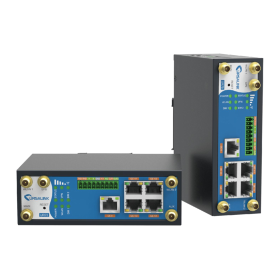
UR75 User Guide 2.2 Product Overview Front Panel Main Cellular Antenna Connector Reset Button LED Indicator Area POWER: Power Indicator STATUS: Status Indicator WLAN: Wi-Fi Indicator VPN: VPN Indicator SIM 1: SIM 1 Status Indicator SIM 2: SIM 2 Status Indicator... -
Page 15: Pin Definition
UR75 User Guide Status VPN is disconnected Static: Wi-Fi is enabled Green Light WLAN WLAN Blinking slowly: sending or receiving data via Wi-Fi (Wi-Fi) Status Wi-Fi is disabled SIM1 or SIM2 is registering or fails to register (or there are no... -
Page 16: Reset Button
UR75 User Guide RS232 RS485 Description Transmit Data Receive Data Data + Data - Ground Digital Input1 Digital Input2 OUT1 Digital Output1 OUT2 Digital Output2 Common Ground Description Positive Negative 2.6 Reset Button Description Function Action STATUS LED Blinking Press and hold the reset button for about 5-15 seconds. -
Page 17: Micro Sd Card/ Ssd Installation
UR75 User Guide B. Put SIM card onto the slot, and then insert the slot back into the hole. 2.8 Micro SD card/ SSD Installation 2.8.1 Micro SD Card Installation A. Unscrew the cover on left panel B. Insert Micro SD card. -
Page 18: Ssd Installation
UR75 User Guide 2.8.2 SSD Installation Before installing SSD, please turn off the power. A. Unscrew the enclosure, and then remove the cover. B. Unscrew the main-board, find the interface on the rear side of the main-board and then insert SSD. -
Page 19: Mounting The Router
It is necessary to choose a standard bracket. Recommended torque for mounting is 1.0 N. m, and the maximum allowed is 1.2 N.m. 2.11 Connect the Router to a Computer Please connect PC to any port among GE 1/1-GE1/4 of UR75 router with Ethernet cable directly. -
Page 20: Installation Of Power Supply And Protective Grounding
Double check antenna connection. Double check if SIM card is inserted and become available. Power on the UR75 industrial cellular router and check indicators status. (1) If Status LED blinks slowly, the system is running properly. If SIM1 or SIM2 indicator is static green, the router is connected to network already. -
Page 21: Chapter 3 Access To Web Gui
This chapter explains how to access to Web GUI of the UR75 router. 3.1 PC Configuration for Web GUI Access to Router Please connect PC to any port among GE 1/1-GE 1/4 of UR75 router directly. PC can obtain an IP address, or you can configure a static IP address manually. -
Page 22: Access To Web Gui Of Router
(Note: remember to click “OK” to finish configuration.) 3.2 Access to Web GUI of Router Ursalink router provides Web-based configuration interface for management. If this is the first time you configure the router, please use the default settings below. Username: admin Password: password IP Address: 192.168.1.1... - Page 23 UR75 User Guide If the SIM card is connected to cellular network with public IP address, you can access WEB GUI remotely via the public IP address when remote access is enabled. If you enter the username or password incorrectly more than 5 times, the login page will be locked for 10 minutes.
-
Page 24: Chapter 4 Web Configuration
UR75 User Guide Chapter 4 Web Configuration 4.1 Status 4.1.1 Overview You can view the system information of the router on this page. Figure 4-1-1-1 System Information Item Description Model Show the model name of router. Serial Number Show the serial number of router. - Page 25 UR75 User Guide Figure 4-1-2-1 Modem Information Item Description Status Show corresponding detection status of module and SIM card. Model Show the model name of cellular module. Current SIM Show the current SIM card used. Signal Level Show the cellular signal level.
-
Page 26: Network
UR75 User Guide Figure 4-1-2-2 Network Status Item Description Status Show the connection status of cellular network. IP Address Show the IP address of cellular network. Netmask Show the netmask of cellular network. Gateway Show the gateway of cellular network. -
Page 27: Wlan (Only Applicable To Wi-Fi Version)
UR75 User Guide Netmask Show the netmask of WAN port. Gateway Show the gateway of WAN port. Show the DNS of WAN port. Show the information on how long the Ethernet cable has been connected on WAN port when WAN function is enabled. Once... - Page 28 UR75 User Guide WLAN Status Item Description Wireless Status Show the wireless status. MAC Address Show the MAC address. Interface Type Show the interface type, such as "AP" or “Client". SSID Show the SSID. Channel Show the wireless channel. Authentication Type Show the authentication type.
-
Page 29: Vpn
UR75 User Guide 4.1.5 VPN You can check VPN status on this page, including PPTP, L2TP, IPsec, OpenVPN and DMVPN. Figure 4-1-5-1 Figure 4-1-5-2... -
Page 30: Routing Information
UR75 User Guide Figure 4-1-5-3 VPN Status Item Description Name Show the name of the VPN tunnel. Status Show the status of the VPN tunnel. Local IP Show the local tunnel IP of VPN tunnel. Remote IP Show the remote tunnel IP of VPN tunnel. -
Page 31: Host List
UR75 User Guide Item Description Routing Table Show the IP address of destination host or destination Destination network. Netmask Show the netmask of destination host or destination network. Gateway Show the IP address of the gateway. Interface Show the outbound interface of the route. -
Page 32: Network
This section describes how to configure the Ethernet port parameters. The UR75 industrial cellular router features 5 Gigabit Ethernet ports, named GE 0, GE 1/1, GE 1/2, GE 1/3 and GE 1/4. Among which, GE 0 is set as WAN port by default for accessing to public network and its property cannot be changed. -
Page 33: Wan
Set the status of Ethernet port; select "up" to enable and "down" to disable. Property UR75: Set the Ethernet port's type, as a WAN port or a LAN port. Set the Ethernet port's speed. The options are "auto", "1000 Mbps", "100 Speed Mbps", and "10 Mbps". - Page 34 UR75 User Guide Secondary DNS Set the secondary DNS. Null Server Enable or disable NAT function. When enabled, a Enable NAT Enable private IP can be translated to a public IP. Table 4-2-1-4 WAN Parameters 1. Static IP Configuration If the external network assigns a fixed IP for the WAN interface, user can select “Static IP” mode.
- Page 35 UR75 User Guide 2. DHCP Client If the external network has DHCP server enabled and has assigned IP addresses to the Ethernet WAN interface, user can select “DHCP client” mode to obtain IP address automatically. Figure 4-2-1-4 DHCP Client Item Description Obtain peer DNS automatically during PPP dialing.
- Page 36 UR75 User Guide Figure 4-2-1-5 PPPoE Item Description Username Enter the username provided by your Internet Service Provider (ISP). Password Enter the password provided by your Internet Service Provider (ISP). Link Detection Set the heartbeat interval for link detection. Range: 1-600.
-
Page 37: Lan
4.2.1.3 LAN 1. LAN Settings LAN setting is used for managing local area network devices which are connected to LAN ports of the UR75, allowing each of them to access the Internet. Click to delete the existing LAN port setting. Click to add a new LAN port. -
Page 38: Wlan (Only Applicable To Wi-Fi Version)
Control communication between VLAN and other networks. Table 4-2-1-9 VLAN Parameters 4.2.1.4 WLAN (Only Applicable to Wi-Fi Version) This section explains how to set the related parameters for Wi-Fi network. UR75 supports 802.11/b/g/n/ac, as AP or client mode. Wi-Fi is optional on UR75. Figure 4-2-1-10... - Page 39 UR75 User Guide WLAN Settings Item Description Enable Enable/disable WLAN. Work Mode Select router's work mode. The options are "Client" and "AP". Scan Click "Scan" button to search the nearby access point. SSID Show SSID. Channel Show wireless channel. Signal Show wireless signal.
-
Page 40: Cellular
SIM1 interface takes precedence by default. A typical use case would be to have SIM1 configured as the primary cellular interface and SIM2 as a backup. If the UR75 cannot connect to the network via SIM1, it will automatically fail over to SIM2. Figure 4-2-1-13... - Page 41 UR75 User Guide Figure 4-2-1-14 General Settings Item Description Default Enable Check the option to enable the corresponding SIM card. Enable Select from "Auto", "4G First", "4G Only", "3G First", "3G Only", "2G Frist", and "2G Only". Auto: connect to the network with the strongest signal Network Type automatically.
- Page 42 UR75 User Guide PING Times Set PING packet numbers in each ICMP detection. Set packet loss rate in each ICMP detection. ICMP Packet Loss Rate detection fails when the preset packet loss rate is exceeded. Table 4-2-1-13 Cellular Parameters Figure 4-2-1-15...
-
Page 43: Loopback
UR75 User Guide automatically when the DI status is changed. Go to "Industrial > I/O > DI" to configure trigger condition. Table 4-2-1-14 Cellular Parameters Dual SIM Strategy Item Description Current SIM Card Select between "SIM1" and "SIM2" as a current SIM card used. -
Page 44: Firewall
UR75 User Guide Figure 4-2-1-16 Loopback Item Description Default Unalterable IP Address 127.0.0.1 Unalterable Netmask 255.0.0.0 Apart from the IP above, user can configure other Multiple IP Null IP addresses. Addresses Table 4-2-1-16 Loopback Parameters 4.2.2 Firewall This section describes how to set the firewall parameters, including ACL, DMZ, Port Mapping and MAC Binding. - Page 45 UR75 User Guide Figure 4-2-2-1 Figure 4-2-2-2 Item Description ACL Setting Select from "Accept" and "Deny". Default Filter Policy The packets which are not included in the access control list will be processed by the default filter policy. Access Control List Type Select type from "Extended"...
-
Page 46: Dmz
UR75 User Guide Destination Port Set destination port number. Range: 1-65535. Start Destination Port Set start destination port number. Range: 1-65535. End Destination Port Set end destination port number. Range: 1-65535. More Details Show information of the port. Interface List Interface Select network interface for access control. -
Page 47: Mac Binding
UR75 User Guide Figure 4-2-2-4 Port Mapping Item Description Specify the host or network which can access local IP address. Source IP 0.0.0.0/0 means all. Enter the TCP or UDP port from which incoming packets are Source Port forwarded. Range: 1-65535. -
Page 48: Qos
UR75 User Guide MAC Binding List Item Description MAC Address Set the binding MAC address. IP Address Set the binding IP address. Fill in a description for convenience of recording the meaning Description of the binding rule for each piece of MAC-IP. -
Page 49: Dhcp
IP address and other information. 4.2.4.1 DHCP Server The UR75 can be set as a DHCP server to distribute IP address when a host logs on and ensures each host is supplied with different IP addresses. DHCP Server has simplified some previous network management... - Page 50 UR75 User Guide Figure 4-2-4-1 DHCP Server Item Description Default Enable Enable or disable DHCP server. Enable Interface Select interface, e.g. GE1. bridge0 Start Define the beginning of the pool of IP addresses which 192.168.1.100 Address will be leased to DHCP clients.
-
Page 51: Dhcp Relay
UR75 User Guide 4.2.4.2 DHCP Relay The UR75 can be set as DHCP Relay to provide a relay tunnel to solve the problem that DHCP Client and DHCP Server are not in the same subnet. Figure 4-2-4-2 DHCP Relay Item... -
Page 52: Link Failover
UR75 User Guide Username Enter the username for DDNS register. User ID Enter User ID of the custom DDNS server. Password Enter the password for DDNS register. Server Enter the name of DDNS server. Hostname Enter the hostname for DDNS. -
Page 53: Sla
UR75 User Guide Configuration Steps Define one or more SLA operations (ICMP probe). Define one or more track objects to track the status of SLA operation. Define applications associated with track objects, such as VRRP, WAN failover or static routing. -
Page 54: Track
UR75 User Guide Table 4-2-6-1 SLA Parameters 4.2.6.2 Track Track setting is designed for achieving linkage among SLA module, Track module and Application module. Track setting is located between application module and SLA module with main function of shielding the differences of various SLA modules and providing unified interfaces for application module. -
Page 55: Vrrp
UR75 User Guide When interface is down or SLA probing fails, it will wait according to the time set here before Negative Delay (s) actually changing its status to Down. Range: 0-180 (0 refers to immediate switching). When failure recovery occurs, it will wait... - Page 56 UR75 User Guide Figure 4-2-6-3 VRRP Item Description Default Enable Enable or disable VRRP. Disable Interface Select the interface of Virtual Router. None Virtual Router ID User-defined Virtual Router ID. Range: 1-255. None Virtual IP Set the IP address of Virtual Router.
-
Page 57: Wan Failover
Trace detection, select the defined track ID or Track ID None blank character. Table 4-2-6-3 VRRP Parameters Note: for UR75, if you select “bridge0” as interface, you must select a track ID, otherwise VRRP status won’t show correctly. Related Configuration Example VRRP Application Example 4.2.6.4 WAN Failover WAN failover refers to failover between Ethernet WAN interface and cellular interface. -
Page 58: Routing
UR75 User Guide When the primary interface switches from failed detection to successful detection, Up Delay (s) switching can be delayed based on the set time. Range: 0-180 (0 refers to immediate switching). When the primary interface switches from successful detection to failed detection,... -
Page 59: Rip
UR75 User Guide Static Routing Item Description Destination Enter the destination IP address. Netmask Enter the subnet mask of destination address. Interface The interface through which the data can reach the destination address. IP address of the next router that will be passed by before the input data Gateway reaches the destination address. - Page 60 UR75 User Guide Figure 4-2-7-2 Description Item Enable Enable or disable RIP. It defines the interval to send routing updates. Range: 5-2147483647, Update Timer in seconds. It defines the routing aging time. If no update package on a routing is...
- Page 61 UR75 User Guide Metric Set metric after "Redistribute Static" is enabled. Range: 0-16. Redistribute OSPF Check to enable. Metric Set metric after "Redistribute OSPF" is enabled. Range: 0-16. Table 4-2-7-2 RIP Parameters Figure 4-2-7-3 Description Item Distance/Metric Management Set the administrative distance that a RIP route learns. Range: Distance 1-255.
-
Page 62: Ospf
UR75 User Guide IP Address Set the IP address of RIP route. Netmask Set the netmask of RIP route. ACL Name Set ACL name of RIP route. The metric of received route or sent route from the interface. Metric Range: 0-16. - Page 63 UR75 User Guide no Router ID configured, the system will automatically select an IP address of interface as the Router ID. The selection order is as follows: If a Loopback interface address is configured, then the last configured IP address of Loopback interface will be used as the Router ID;...
- Page 64 UR75 User Guide Router ID Router ID (IP address) of the originating LSA. ABR Type Select from cisco, ibm, standard and shortcut. RFC1583 Compatibility Enable/Disable. Enable/Disable OSPF Opaque-LSA LSA: a basic communication means of the OSPF routing protocol for the Internet Protocol (IP).
- Page 65 UR75 User Guide time should be increased before transmission the aging time of LSA. This configuration needs to be further considered on the low-speed link. Range: 1-65535 Interface Advanced Options Interface Select interface. Network Select OSPF network type. Cost Set the cost of running OSPF on an interface. Range: 1-65535.
- Page 66 UR75 User Guide Area ID The area ID of original LSA's router. Area Area ID Set the ID of the OSPF area (IP address). Select from "Stub" and "NSSA". Area The backbone area (area ID 0.0.0.0) cannot be set as "Stub" or "NSSA".
-
Page 67: Routing Filtering
UR75 User Guide Set the interval time for sending Hello packets through the interface. Range: Hello Interval 1-65535. The dead interval time for sending Hello packets through the interface. Range: Dead Interval 1-65535. The retransmission interval time for re-sending LSA. -
Page 68: Vpn
Virtual Private Networks, also called VPNs, are used to securely connect two private networks together so that devices can connect from one network to the other network via secure channels. UR75 supports DMVPN, IPsec, GRE, L2TP, PPTP, OpenVPN, as well as GRE over IPsec and L2TP over IPsec. 4.2.8.1 DMVPN... - Page 69 UR75 User Guide A dynamic multi-point virtual private network (DMVPN), combining mGRE and IPsec, is a secure network that exchanges data between sites without passing traffic through an organization's headquarter VPN server or router. Figure 4-2-8-1 DMVPN Item Description Enable Enable or disable DMVPN.
-
Page 70: Ipsec
UR75 User Guide GRE Key GRE tunnel key. Negotiation Mode Select from "Main" and "Aggressive". Authentication Select from "DES", "3DES", "AES128", "AES192" and "AES256". Algorithm Encryption Algorithm Select from "MD5" and "SHA1". Select from "MODP768_1", "MODP1024_2" and DH Group "MODP1536_5". - Page 71 UR75 User Guide Figure 4-2-8-2 IPsec Item Description Enable Enable IPsec tunnel. A maximum of 3 tunnels is allowed. IPsec Gateway Address Enter the IP address or domain name of remote IPsec server. IPsec Mode Select from "Tunnel" and "Transport".
- Page 72 UR75 User Guide Figure 4-2-8-3 IKE Parameter Item Description IKE Version Select from "IKEv1" and "IKEv2". Negotiation Mode Select from "Main" and "Aggressive". Encryption Algorithm Select from "DES", "3DES", "AES128", "AES192" and "AES256". Authentication Select from "MD5" and " SHA1"...
-
Page 73: Gre
UR75 User Guide Select from "DES_MD5", "DES_SHA1", "3DES_MD5", "3DES_SHA1", "AES128_MD5", "AES128_SHA1", SA Algorithm "AES192_MD5", "AES192_SHA1", "AES256_MD5" and "AES256_SHA1". Select from "NULL", "MODP768_1" , "MODP1024_2" and PFS Group "MODP1536_5". Lifetime (s) Set the lifetime of IPsec SA. Range: 60-86400. DPD Interval Time(s) Set DPD interval time to detect if the remote side fails. -
Page 74: L2Tp
UR75 User Guide Figure 4-2-8-4 Item Description Enable Check to enable GRE function. Remote IP Address Enter the real remote IP address of GRE tunnel. Local IP Address Set the local IP address. Local Virtual IP Address Set the local tunnel IP address of GRE tunnel. - Page 75 UR75 User Guide by an Internet service provider (ISP) to enable the operation of a virtual private network (VPN) over the Internet. Figure 4-2-8-5 L2TP Item Description Enable Check to enable L2TP function. Remote IP Address Enter the public IP address or domain name of L2TP server.
- Page 76 UR75 User Guide Figure 4-2-8-6 Advanced Settings Item Description Set tunnel IP address of L2TP client. Client will obtain tunnel IP Local IP Address address automatically from the server when it's null. Peer IP Address Enter tunnel IP address of L2TP server.
-
Page 77: Pptp
UR75 User Guide 4.2.8.5 PPTP Point-to-Point Tunneling Protocol (PPTP) is a protocol that allows corporations to extend their own corporate network through private "tunnels" over the public Internet. Effectively, a corporation uses a wide-area network as a single large local area network. - Page 78 UR75 User Guide Figure 4-2-8-8 PPTP Advanced Settings Item Description Local IP Address Set IP address of PPTP client. Peer IP Address Enter tunnel IP address of PPTP server. Enable NAT Enable the NAT faction of PPTP. Enable MPPE Enable MPPE encryption.
-
Page 79: Openvpn Client
UR75 User Guide Related Configuration Example PPTP Application Example 4.2.8.6 OpenVPN Client OpenVPN is an open source virtual private network (VPN) product that offers a simplified security framework, modular network design, and cross-platform portability. Advantages of OpenVPN include: Security provisions that function against both active and passive attacks. - Page 80 UR75 User Guide OpenVPN Client Item Description Enable Enable OpenVPN client. A maximum of 3 tunnels is allowed. Protocol Select from "UDP" and "TCP". Remote IP Address Enter remote OpenVPN server's IP address or domain name. Enter the listening port number of remote OpenVPN server.
-
Page 81: Openvpn Server
UR75 User Guide 4.2.8.7 OpenVPN Server The UR75 supports OpenVPN server to create secure point-to-point or site-to-site connections in routed or bridged configurations and remote access facilities. Figure 4-2-8-10 Figure 4-2-8-11... - Page 82 UR75 User Guide OpenVPN Server Item Description Enable Enable/disable OpenVPN server. Protocol Select from TCP and UDP. Port Fill in listening port number. Range: 1-65535. Enter WAN IP address or LAN IP address. Leaving it blank refers Listening IP to all active WAN IP and LAN IP address.
-
Page 83: Certifications
UR75 User Guide 4.2.8.8 Certifications User can import/export certificate and key files for OpenVPN and IPsec on this page. Figure 4-2-8-12 OpenVPN Client Item Description Import/Export CA certificate file. Public Key Import/Export public key file. Private Key Import/Export private key file. -
Page 84: System
UR75 User Guide OpenVPN Server Item Description Import/Export CA certificate file. Public Key Import/Export public key file. Private Key Import/Export private key file. Import/Export DH key file. Import/Export TA key file. Import/Export CRL. Preshared Key Import/Export static key file. Table 4-2-8-12 OpenVPN Server Parameters... - Page 85 UR75 User Guide Figure 4-3-1-1 General Item Description Default System Hostname User-defined router name, needs to start with a letter. URSA Web Login You need to log in again if it times out. Range: 100-3600. 1800 Timeout (s) Access Service Local Access the router locally.
-
Page 86: Account Management
UR75 User Guide Item Description Default HTTPS Certificates Click "Browse" button, choose certificate file on the PC, and then click "Import" button to upload the file into Certificate router. Click "Export" button will export the file to the PC. Click "Delete" button will delete the file. - Page 87 UR75 User Guide Note: to ensure that the router runs with the correct time, it’s recommended that you set the system time when configuring the router. Figure 4-3-1-3 Figure 4-3-1-4 Figure 4-3-1-5 System Time Item Description Current Time Show the current system time.
-
Page 88: Smtp
UR75 User Guide type. Sync with Browser Synchronize time with browser. Browser Time Show the current time of browser. Set up Manually Manually configure the system time. Synchronize time with NTP server so as to achieve time Sync with NTP Server synchronization of all devices equipped with a clock on network. -
Page 89: Phone
UR75 User Guide Enable Enable or disable SMTP client function. Email Address Enter the sender's email account. Password Enter the sender's email password. SMTP Server Address Enter SMTP server's domain name. Port Enter SMTP server port. Range: 1-65535. Enable TLS Enable or disable TLS encryption. -
Page 90: Storage
UR75 User Guide Phone Item Description Phone Number List Number Enter the telephone number. Digits, "+" and "-" are allowed. Description The description of the telephone number. Phone Group Group ID Set number for phone group. Range: 1-100. Description The description of the phone group. -
Page 91: User Management
UR75 User Guide 4.3.2 User Management This section describes how to create common user accounts. The common user permission includes Read-Only and Read-Write. Figure 4-3-2-1 User Management Item Description Enter a new username. You can use characters such as a-z, 0-9, "_", "-", "$". -
Page 92: Snmp
UR75 User Guide 4.3.3.1 SNMP The UR75 supports SNMPv1, SNMPv2c and SNMPv3 version. SNMPv1 and SNMPv2c employ community name authentication. SNMPv3 employs authentication encryption by username and password. Figure 4-4-3-1 SNMP Settings Item Description Enable Enable or disable SNMP function. -
Page 93: Vacm
UR75 User Guide MIB View Item Description View Name Set MIB view's name. View Filter Select from "Included" and "Excluded". View OID Enter the OID number. Included You can query all nodes within the specified MIB node. Excluded You can query all nodes except for the specified MIB node. -
Page 94: Trap
UR75 User Guide 4.3.3.4 Trap This section explains how to enable network monitoring by SNMP trap. Figure 4-3-3-4 SNMP Trap Item Description Enable Enable or disable SNMP Trap function. SNMP Version Select SNMP version; support SNMP v1/v2c/v3. Server Address Fill in NMS's IP address or domain name. -
Page 95: Aaa
UR75 User Guide 4.3.4 AAA AAA access control is used for visitors control and the available corresponding services once access is allowed. It adopts the same method to configure three independent safety functions. It provides modularization methods for following services: Authentication: verify if the user is qualified to access to the network. -
Page 96: Ldap
UR75 User Guide Figure 4-3-4-2 TACACS+ Item Description Enable Enable or disable TACACS+. Server IP Address Fill in the TACACS+ server IP address/domain name. Server Port Fill in the TACACS+ server port. Range: 1-65535. Fill in the key consistent with that of TACACS+ server in order to get connected with TACACS+ server. -
Page 97: Authentication
UR75 User Guide LDAP Item Description Enable Enable or Disable LDAP. Fill in the LDAP server's IP address/domain name. The Server IP Address maximum count is 10. Server Port Fill in the LDAP server's port. Range: 1-65535 Base DN The top of LDAP directory tree. -
Page 98: Device Management
UR75 User Guide 4.3.5 Device Management You can connect the device to the device management platform on this page so as to manage the router. Figure 4-3-5-1 Device Management Item Description Show the connection status between the router and device Status management platform. -
Page 99: Events Settings
UR75 User Guide Figure 4-3-6-1 Events Item Description Mark as Read Mark the selected event alarm as read. Delete Delete the selected event alarm. Mark All as Read Mark all event alarms as read. Delete All Alarms Delete all event alarms. -
Page 100: Industrial Interface
Events Application Example 4.4 Industrial Interface The UR75 router is capable of connecting with terminals through industrial interfaces so as to realize wireless communication between terminals and remote data center. There are two types of the router’s industrial interface: serial port (RS232 and RS485) and I/O (digital input and digital output). -
Page 101: I/O
UR75 User Guide RS232*1 RS485*1 DI*2 DO*2 Description Transmit Data Receive Data Data + Data - Ground Digital Input1 Digital Input2 OUT1 Digital Output1 OUT2 Digital Output2 Common Ground Table 4-4-1 Pinouts Definition RS232 adopts full-duplex communication. It’s generally used for communication within 20m. - Page 102 UR75 User Guide Item Description Enable Enable or disable DI. Mode Options are "High Level", "Low Level", and "Counter". Set the duration of high/low level in digital input. Range: Duration (ms) 1-10000. Condition Select from "Low->High", and "High-> Low". The counter value will increase by 1 if digital input's status Low->High...
-
Page 103: Serial Port
UR75 User Guide 4.4.1.2 DO This section describes how to configure digital output mode. Figure 4-4-1-2 Item Description Enable Enable or disable DO. Mode Select from "High Level", "Low Level", and "Pulse". Duration (*10ms) Set duration of high/low level on digital output. Range: 1-10000. - Page 104 UR75 User Guide Figure 4-4-2-1 Serial Settings Item Description Default Enable Enable or disable serial port function. Disable Serial Type Serial Port 1 is a RS232 port. Serial Port 2 is a RS485 port. Range is 300-230400. Same with the baud rate of the...
- Page 105 UR75 User Guide Figure 4-4-2-2 DTU Mode Item Description Default Select from "None", "Transparent", "Modbus", and "TCP server". Transparent: the routed is used as TCP client/UDP and transmits data transparently. TCP server: the router is used as TCP server and transmits data DTU Protocol transparently.
-
Page 106: Modbus Tcp
UR75 User Guide Item Description Default Transparent Protocol Select "TCP" or "UDP" protocol. After TCP client is connected with TCP server, the client will send Keepalive Interval heartbeat packet by TCP regularly to keep alive. The interval range is 1-3600, in seconds. -
Page 107: Modbus Tcp
UR75 User Guide 4.4.3.1 Modbus TCP You can define the address of the DI and DO ports so as to poll DI’s status and control DO’s status via Modbus TCP protocol. Figure 4-4-3-1 Modbus TCP Item Description Default Enable Enable/disable Modbus TCP. -
Page 108: Channel
UR75 User Guide Figure 4-4-4-1 Modbus Master Item Description Default Enable Enable/disable Modbus master. Set the interval for reading remote channels. When the read cycle ends, the commands which haven't been sent out will be Read Interval/s discard, and the new read cycle begins. If it is set to 0, the device will restart the new read cycle after all channels have been read. - Page 109 UR75 User Guide Figure 4-4-4-2 Channel Setting Item Description Name Set the name to identify the remote channel. It cannot be blank. Slave ID Set Modbus slave ID. Address The starting address for reading. Number The address number for reading.
- Page 110 UR75 User Guide Figure 4-4-4-3 Alarm Setting Item Description Name Set the same name with the channel name to identify the remote channel. Condition The condition that triggers alert. Set the min. value to trigger the alert. When the actual value is less than this Min.
-
Page 111: Gps
UR75 User Guide 4.4.5 GPS This section gives you a detailed introduction to GPS settings, including GPS IP forwarding and GPS serial forwarding. 4.4.5.1 GPS When you want to receive GPS data, you should enable GPS function on this page. -
Page 112: Gps Serial Forwarding
UR75 User Guide Figure 4-4-5-3 GPS IP Forwarding Item Description Default Enable Forward the GPS data to the client or server. Disable Select connection type of the router. The options are "Client" Type Client and "Server". Select protocol of data transmission. The options are "TCP"... -
Page 113: Maintenance
UR75 User Guide Figure 4-4-5-4 GPS Serial Forwarding Item Description Default Enable Forward the GPS data to the preset serial port. Disable Select the serial port to receive GPS data. The options are Serial Type "serial 1" and "serial 2". -
Page 114: Traceroute
UR75 User Guide Figure 4-5-1-1 PING Item Description Ping outer network from the router. Host Table 4-5-1-1 IP Ping Parameters 4.5.1.2 Traceroute Traceroute tool is used for troubleshooting network routing failures. Figure 4-5-1-2 Traceroute Item Description Host Address of the destination host to be detected. -
Page 115: Schedule
UR75 User Guide 4.5.2 Schedule This section explains how to configure scheduled reboot on the router. Figure 4-5-2-1 Schedule Item Description Schedule Select schedule type. Reboot Reboot the router regularly. Frequency Select the frequency to execute the schedule. Hour & Minute Select the time to execute the schedule. -
Page 116: Log Settings
UR75 User Guide Figure 4-5-3-1 System Log Item Description Download Download log file. View recent (lines) View the specified lines of system log. Clear Log Clear the current system log. Table 4-5-3-1 System Log Parameter 4.5.3.2 Log Settings This section explains how to enable remote log server and local log setting. -
Page 117: Upgrade
UR75 User Guide Log Settings Item Description Remote Log Server With “Remote Log Server” enabled, router will send all system Enable logs to the remote server. Syslog Server Address Fill in the remote system log server address (IP/domain name). Port Fill in the remote system log server port. -
Page 118: Backup And Restore
UR75 User Guide Upgrade Item Description Firmware Version Show the current firmware version. Reset Configuration When this option is checked, the router will be reset to factory defaults after to Factory Default upgrade. Click "Browse" button to select the new firmware file, and click "Upgrade" to Upgrade Firmware upgrade firmware. -
Page 119: Reboot
UR75 User Guide Click "Backup" to export the current configuration file to the Backup Click "Reset" button to reset factory default settings. Router Reset will restart after reset process is done. Table 4-5-5-1 Backup and Restore Parameters Related Configuration Example... -
Page 120: Python
UR75 User Guide and readability. As an interpreted language, Python has a design philosophy that emphasizes code readability, notably using whitespace indentation to delimit code blocks rather than curly brackets or keywords, and a syntax that allows programmers to express concepts in fewer lines of code than it’s used in other languages such as C++ or Java. -
Page 121: App Manager Configuration
UR75 User Guide 4.6.1.2 App Manager Configuration Figure 4-6-1-2 AppManager Configuration Item Description After enabling Python AppManager, user can click "View" button on the "Python" Enable webpage to view the application status managed by AppManager. App Management Show the ID of the imported App. - Page 122 UR75 User Guide Python APP Item Description App Package Select App package and import. App Name Select App to import configuration. App Configuration Select configuration file and import. Debug File Export script file. Debug Script Select Python script to be debugged and import.
-
Page 123: Chapter 5 Application Examples
It is strongly recommended that you change the default username and password of the administrator account when you log in Ursalink Router’s WEB GUI page at first time for the sake of security. Example: change the username and password of administrator account to “uradmin” and “URpassword”. -
Page 124: System Time Management
UR75 User Guide Configuration procedures are listed as blow. Go to “System > User Management > User Management”. Click “ ” to add a new common user. Set “Username”, “Password”, and “Permission” as below. Click “Save” button, and then click “Apply” on the top-right corner to make the changes take effect. - Page 125 UR75 User Guide Set up time by manual Go to “System > General Settings > System Time”, set time zone as “8 China (Beijing)” and Sync Type as “Set up Manually”. Select the correct local time. And click “Save” button.
-
Page 126: Backup And Restore Configuration
UR75 User Guide 5.4 Backup and Restore Configuration A. Backup Configuration Go to “Maintenance > Backup and Restore > Backup and Restore”. Click “Backup” button under “Backup running-config”. Then the current configuration file will be downloaded to the “Downloads” folder of the PC. -
Page 127: Restore Factory Defaults
UR75 User Guide 5.5 Restore Factory Defaults 5.5.1 Via Web Interface Log in web interface, and go to “Maintenance > Backup and Restore”. Click “Reset” button under the “Restore Factory Defaults”. You will be asked to confirm if you’d like to reset it to factory defaults. Then click “Reset” button. -
Page 128: Via Hardware
UR75 User Guide Please wait till the login page pops up again, which means the router has already been reset to factory defaults successfully. Related Topic Restore Factory Defaults 5.5.2 Via Hardware... -
Page 129: Firmware Upgrade
5.6 Firmware Upgrade It is suggested that you contact Ursalink technical support first before you upgrade router firmware. After getting firmware file from Ursalink technical support, please refer to the following steps to complete the upgrade. Go to “Maintenance > Upgrade”. - Page 130 UR75 User Guide Related Topic Upgrade...
-
Page 131: Events Application Example
UR75 User Guide 5.7 Events Application Example Example In this section, we will take an example of sending alarm messages by email when the following events occur and recording the event alarms on the Web GUI. Events Actions to make events occur (for test) Cellular network is connected. -
Page 132: Schedule Application Example
Related Topics Events Email Setting 5.8 Schedule Application Example Through schedule configuration, the UR75 can be set to reboot at preset time every day. Example Configure router to reboot at 0:00 every day. Configuration Steps Go to “Maintenance > Schedule > Schedule”. -
Page 133: Logs And Diagnostics
Related Topic Schedule Setting 5.9 Logs and Diagnostics System log of the UR75 supports 3 types of output method, including Web and Remote Log Server. Application 1 Obtain system log on Web. Go to “Maintenance > Log > System log”, and you will see the log is listed in the box. -
Page 134: Snmp Application Example
System Log 5.10 SNMP Application Example Before you configure SNMP parameters, please download the relevant “MIB” file from the UR75’s WEB GUI first, and then upload it to any software or tool which supports standard SNMP protocol. Here take “ManageEngine MibBrowser Free Tool” as an example access the router to query cellular information. - Page 135 UR75 User Guide Click the “+” button beside “URSA-ROUTER-MIB”, which is under the “Loaded MibModules” menu, and find “usCellularinfo”. And then you will see the OID of cellular info is “.1.3.6.1.4.1.50234”, which will be filled in the MIB View settings.
- Page 136 UR75 User Guide Go to “System > SNMP > MIB View”. Click to add a new MIB view and define the view to be accessed from the outside network. Then click “Save” button. Go to “System > SNMP > VACM”. Click to add a new VACM setting to define the access authority for the specified view from the specified outside network.
-
Page 137: Lan Management
5.11 LAN Management In LAN Settings, you can configure IP and other parameters of the Ethernet ports which are set as “LAN”. Example GE 1 port of UR75 is configured as “LAN”. Parameters are listed below. Interface IP Address Netmask GE 1 192.168.1.1... -
Page 138: Network Connection
If both cellular interfaces are enabled, SIM1 interface takes precedence as default. Example We are about to take an example of inserting a SIM card into SIM1 slot of the UR75 and configuring the router to get Internet access through cellular. - Page 139 UR75 User Guide Click “Save” and “Apply” for configuration to take effect. Note: If you select “Auto”, the router will obtain ISP information from SIM card to set APN, Username, and Password automatically. This option will only be taken effect when the SIM card is issued from well-known ISP.
-
Page 140: Ethernet Wan Connection
When both “WAN” and “Cellular” interfaces are enabled and available, cellular interfaces will take precedence by default. Example GE 0 of the UR75 is configured as “WAN”, and the port is connected with Ethernet cable to get Internet access. Configuration Steps... - Page 141 UR75 User Guide Go to “Network > Interface > WAN” to configure WAN parameters. The following examples of static IP type, DHCP Client type, and PPPoE type are listed for your reference. (1) Static IP (2) DHCP Client...
- Page 142 UR75 User Guide (3) PPPoE...
-
Page 143: Wan Failover/Backup Application Example
5.13.1 Dual SIM Backup Example In this section we will take an example of inserting SIM cards into the UR75. When one SIM fails, router will try to connect with the other SIM as backup link. Configuration Steps Go to “Network > Interface > Cellular” to enable SIM1 and SIM2. Leave the network type as “Auto”... - Page 144 UR75 User Guide Then click “Save” and “Apply” button. Go to “Status > Cellular”, and you will see the router is connected to the network via SIM1.
-
Page 145: Wan Failover
Application Example An UR75 router is connected with PC via GE 1 (LAN) port, and GE 0 (WAN) of the UR75 is connected to Internet via wired network. Configure WAN failover in the router so that it can failover to cellular to get Internet access in case of the malfunction of wired network and failback to wired network when it’s... - Page 146 Go to “Network > Interface > WAN” and configure wired WAN connection as below. When configuration is done, click “Save & Apply” button. Then confirm if it is able to visit Internet on PC through the UR75. Go to “Network > Interface > Cellular”, enable cellular settings and click “Save” button.
- Page 147 UR75 User Guide Go to “Network > Link Failover > SLA” and configure SLA probe. The default probe type is ICMP. The destination address is the host address which can be probed by ICMP in public network or private network. Other parameters can be kept as default value.
- Page 148 UR75 User Guide Track settings. Go to “Network > Link Failover > WAN Failover” and select “GE0” as main interface, “cellular0” as backup interface. Other parameters can be kept as default value. After all configurations are done, click “Apply” button.
-
Page 149: Wi-Fi Application Example (Only Applicable To Wi-Fi Version)
5.14 Wi-Fi Application Example (Only Applicable to Wi-Fi Version) 5.14.1 AP Mode Application Example Configure UR75 as AP to allow connection from users or devices. Configuration Steps Go to “Network > Interface > WLAN” to configure wireless parameters as below. -
Page 150: Client Mode
Use a smart phone to connect by SSID “Wi-Fi Test”. Go to “Status > WLAN”, and you can check the AP settings and information of the connected client/user. 5.14.2 Client Mode Application Example Configure UR75 as Wi-Fi client to connect to an access point to have Internet access. - Page 151 UR75 User Guide Configuration Steps Go to “Network > Interface > WLAN” to configure wireless as below. Click “Save” and “Apply” button after all configurations are done. Go to “Status > WLAN”, and you can check the wireless settings, connection status and the information of the access point.
-
Page 152: Vrrp Application Example
UR75 routers can be deployed as VRRP backup group, so as to improve network reliability. VRRP group: GE 0 ports of the UR75 Router A and Router B are connected to the Internet via wired network. And GE 1 ports of them are connected to a switch. Virtual IP is 192.168.1.254/24. - Page 153 UR75 User Guide Go to “Network > Link Failover > SLA” and configure SLA probe. The default probe type is ICMP. The destination address is the host address which can be probed by ICMP in public network or private network. Other parameters can be kept as default value.
- Page 154 UR75 User Guide Go to “Network > Link Failover > VRRP” and configure VRRP parameters as below. Router B Configuration Go to “Network > Interface > WAN” and configure wired WAN connection as below.
- Page 155 UR75 User Guide Go to “Network > Link Failover > SLA” and configure SLA probe. The default probe type is ICMP. The destination address is the host address which can be probed by ICMP in public network or private network. Other parameters can be kept as default value.
- Page 156 UR75 User Guide Go to “Network > Link Failover > VRRP” and configure VRRP parameters as below. Once you complete all configurations, click “Apply” button on the top-right corner to make changes take effect. Result: normally, A is the master router, used as the default gateway. When the power of Router A is down or Router A suffers from failure, Router B will become the master router, used as the default gateway.
-
Page 157: Static Routing Application Example
Static routing can build up the communication between 2 different private networks. Application Example The UR75 Router A and the UR75 Router B are connected with GE 0 (WAN) port as shown in the following topological graph. Add static routing in A and B to make PC1 and PC2 communicate with each other. -
Page 158: Dynamic Routing Application Example
5.17 Dynamic Routing Application Example Example The UR75 Router A and the UR75 Router B are connected with GE 0 (WAN) port. Refer to the below topological graph. Add dynamic routing in Router A and Router B to establish communication between PC1 and PC2. - Page 159 UR75 User Guide Go to “Network > Interface > LAN” and configure LAN parameters. Go to “Network > Routing > RIP” and configure dynamic routing parameters. Click “Save” and “Apply” button. Router B Configuration Go to “Network > Interface > WAN” and configure WAN parameters.
- Page 160 UR75 User Guide Go to “Network > Interface > LAN” and configure LAN parameters. Go to “Network > Routing > RIP” and configure dynamic routing parameters.
-
Page 161: Nat Application Example
5.18 NAT Application Example Example An UR75 router can access Internet via cellular. GE 1 port is connected with a Web server whose IP address is 192.168.1.2 and port is 8000. Configure the router to make public network access the server. - Page 162 UR75 User Guide Configuration Steps Go to “Network > Firewall > ACL” to configure access control list. Click “ ” button to set parameters as below. Then click “Save” button. Configure interface list. Then click “Save” and “Apply” button. Related Topic...
-
Page 163: Qos Application Example
5.20 QoS Application Example Example Configure the UR75 router to distribute local preference to different FTP download channels. The total download bandwidth is 75000 kbps. Note: the “Total Download Bandwidth” should be less than the real maximum bandwidth of WAN or cellular interface. - Page 164 UR75 User Guide PLC is connected with the UR75 via RS232. Then enable DTU function of the UR75 to make a remote TCP server communicate with PLC. Refer to the following topological graph. Serial Parameters of the PLC Baud Rate...
- Page 165 UR75 User Guide Configure TCP server IP and port. Once you complete all configurations, click “Save” and “Apply” button. Start TCP server on PC. Take “Netassist” test software as example. Make sure port mapping is already done.
- Page 166 UR75 User Guide Connect the UR75 to PC via RS232 for PLC simulation. Then start “sscom” software on the PC to test communication through serial port. After connection is established between the UR75 and the TCP server, you can send data between sscom and netassit.
-
Page 167: Pptp Application Example
Serial Port 5.22 PPTP Application Example Example Configure the UR75 as PPTP client to connect to a PPTP server in order to have data transferred securely. Refer to the following topological graph. Configuration Steps Go to “Network > VPN > PPTP”, configure PPTP server IP address, username and password provided by PPTP server. - Page 168 UR75 User Guide If you want to access peer subnet such as 192.168.3.0/24, you need to configure the subnet and mask to add the route. Check “Show Advanced” option, and you will see the advanced settings.
- Page 169 UR75 User Guide If the PPTP server requires MPPE encryption, then you need to check “Enable MPPE” option. If the PPTP server assigns fixed tunnel IP to the client, then you can fill in the local tunnel IP and remote tunnel IP, shown as below.
Need help?
Do you have a question about the UR75 and is the answer not in the manual?
Questions and answers