Table of Contents
Advertisement
USER MANUAL
NI roboRIO
RIO Device for Robotics
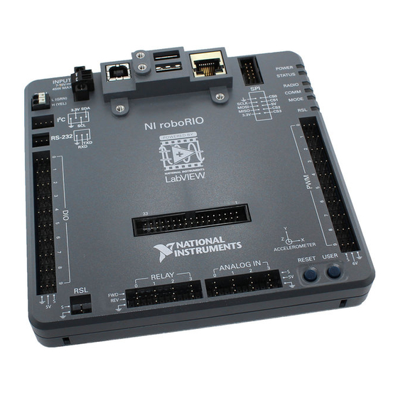
The NI roboRIO is a portable reconfigurable I/O (RIO) device that students can use to design
control, robotics, and mechatronics systems used in the FIRST Robotics Competition (FRC).
This document contains pinouts, connectivity information, dimensions, and mounting
instructions for the NI roboRIO. The NI roboRIO provides the I/O shown in Figure 1 and
connects to a host computer over USB and 10/100 Ethernet.
4
3
2
1
1
Digital input and output (DIO) port
2
RS-232 port
2
3
I
C port
4
CAN port
5
Power connector
6
USB Device port
7
USB Host retention mount
8
USB Host ports
9
Ethernet port
Figure 1. NI roboRIO Features
5
6
7
INPUT
INPUT
7-16V
7-16V
CAN
CAN
L (GRN)
L (GRN)
H (YEL)
H (YEL)
3.3V SDA
3.3V SDA
2
I
C
SCL
SCL
NI roboRIO
NI roboRIO
RS-232
RS-232
TXD
TXD
RXD
RXD
33
33
RELAY
RELAY
RSL
RSL
0
1
2
S
FWD
FWD
5V
5V
REV
REV
S
18
17
8
9
10
SPI
SPI
14
SCLK
SCLK
MOSI
MOSI
MISO
MISO
3.3V
3.3V
1
Y
Z
X
ACCELEROMETER
ACCELEROMETER
ANALOG IN
ANALOG IN
RESET
RESET
3
0
1
2
3
S
5V
5V
16
15
10 Serial peripheral interface bus (SPI) port
11 LEDs
12 Pulse-width modulation (PWM) port
13 myRIO Expansion Port (MXP)
14 MXP retention mount
15 User and Reset buttons
16 Analog input (AI) port
17 Relay port
18 Robot signal light (RSL) port
POWER
POWER
STATUS
STATUS
RADIO
RADIO
11
COMM
COMM
CS0
CS0
CS1
CS1
MODE
MODE
5V
5V
CS2
CS2
CS3
CS3
RSL
RSL
12
13
USER
USER
S
6V
6V
Advertisement
Table of Contents

Subscribe to Our Youtube Channel
Related Manuals for National Instruments NI roboRIO


Summary of Contents for National Instruments NI roboRIO
- Page 1 NI roboRIO RIO Device for Robotics The NI roboRIO is a portable reconfigurable I/O (RIO) device that students can use to design control, robotics, and mechatronics systems used in the FIRST Robotics Competition (FRC). This document contains pinouts, connectivity information, dimensions, and mounting instructions for the NI roboRIO.
-
Page 2: Table Of Contents
Electromagnetic Compatibility Guidelines................3 Hardware Block Diagram ......................4 Setting Up the NI roboRIO ....................... 5 Wiring Power to the NI roboRIO ..................5 Powering On the NI roboRIO ................... 5 Connecting the NI roboRIO to a Network................ 6 Preparing the NI roboRIO for Competition ..............6 User Power........................ -
Page 3: Safety Information
Furthermore, any modifications to the product not expressly approved by National Instruments could void your authority to operate it under your local regulatory rules. -
Page 4: Hardware Block Diagram
Hardware Block Diagram Figure 2 shows the arrangement and functions of NI roboRIO components. Figure 2. NI roboRIO Hardware Block Diagram SPI Port 10/100 Ethernet Device Hosts +3.3 V +5.0 V Port Port Port Xilinx Zynq-7020 Port Power LED +5.0 V Status LED +3.3 V... -
Page 5: Setting Up The Ni Roborio
Requirements section of the NI roboRIO Specifications. The NI roboRIO filters and regulates the supplied power and provides power for all of the I/O and user voltage. The NI roboRIO has one layer of reverse-voltage protection. Complete the following steps to connect a power supply to the chassis. -
Page 6: Connecting The Ni Roborio To A Network
Connecting the NI roboRIO to a Network Connect the NI roboRIO to an Ethernet network using the Ethernet port. Use a standard Category 5 (CAT-5) or better shielded, twisted-pair Ethernet cable to connect the NI roboRIO to an Ethernet hub, router, or directly to a computer. - Page 7 Input Voltage Brownout Behavior The NI roboRIO input voltage range is 7 V to 16 V. The input voltage monitoring circuit monitors the voltage on the input voltage pin. When the input voltage drops to between 4.5 V and 6.8 V, the NI roboRIO enters brownout mode with a staged response, as Table 2 describes.
-
Page 8: Pinouts
Pinouts The following describe the pins and signals on the NI roboRIO ports. Figure 4 and Table 3 describe the MXP pins and signals. Note that some pins carry both primary and secondary functions. Figure 4. MXP Pinout Table 3. MXP Signal Descriptions... -
Page 9: Can Port
CAN bus differential low signal. H (YEL) Input/Output CAN bus differential high signal. The NI roboRIO contains an internal 120 W termination resistor between Note L (GRN) and H (YEL). NI roboRIO User Manual | © National Instruments | 9... -
Page 10: I 2 C Port
UART and RS-232 Lines section for more information. Input Serial receive input with ±15 V input voltage range. Refer to the UART and RS-232 Lines section for more information. — Reference for digital lines. 10 | ni.com | NI roboRIO User Manual... -
Page 11: Dio Port
Output Switched power output to drive RSL when RSLis enabled. The voltage level depends on the connected input voltage. RSL current is limited at 120 mA. — Reference for S. NI roboRIO User Manual | © National Instruments | 11... -
Page 12: Relay Port
Input 0 V to 5 V referenced, single-ended AI channels. Refer to the AI Channels section for more information. Output +5 V power output. — Reference for AI and +5 V power. 12 | ni.com | NI roboRIO User Manual... -
Page 13: Pwm Port
SPI with 3.3 V output, 3.3 V/5 V-compatible input. Refer to the SPI Lines section for more SCLK Output information. MOSI Output MISO Input — Reference for digital lines and +3.3 V and +5.5 V power output. NI roboRIO User Manual | © National Instruments | 13... -
Page 14: Signal Ground References
Interfaces AI Channels The NI roboRIO has AI channels on the MXP and on the AI port. The channels are multiplexed to a single analog-to-digital converter (ADC) that samples all channels. The MXP and the AI port each has four single-ended AI channels, AI0-AI3, which you can use to measure 0-5 V signals. -
Page 15: Dio, Pwm, And Relay Lines
40 kΩ pulldown resistors to ground, as shown in Figure 18. Ω Pulldown Resistors to Ground Figure 18. DIO Lines with 40 k Bus Switch DIO or Other Line FPGA 40 kΩ NI roboRIO User Manual | © National Instruments | 15... -
Page 16: Uart And Rs-232 Lines
You can add a stronger resistor to a DIO line to cause it to float in the opposite direction. UART and RS-232 Lines The NI roboRIO has one UART connected to the UART lines on the MXP and one UART connected to the RS-232 port. -
Page 17: Accelerometer
In safe mode, the NI roboRIO launches only the services necessary for updating configuration and installing software. When the NI roboRIO is in safe mode, you can communicate with it by using the serial lines on the RS-232 serial port. You must configure your serial-port terminal program with the following settings: •... -
Page 18: User Button
The input voltage is too high (greater than 16 V) and all outputs, including the RSL output, are disabled. Yellow Solid Brownout condition detected. The 6 V user rail and outputs are disabled. 18 | ni.com | NI roboRIO User Manual... -
Page 19: Status Led
The Status LED is a single-color yellow LED. The Status LED is off during normal operation. The NI roboRIO runs a power-on self test (POST) when you apply power to the device. During the POST, the Power and Status LEDs turn on. When the Status LED turns off, the POST is complete. -
Page 20: Comm Led
Active. The protocol is active and the driver station is in control of the robot. Yellow Reserved. Mode LED The Mode LED is a tri-color red/green/yellow LED that indicates the mode of the NI roboRIO outputs, as shown in Table 17. Table 17. Mode LED Indications Color State Indication Outputs disabled. -
Page 21: Rsl (Safety) Led
RSL (Safety) LED The RSL LED is a single-color yellow LED that functions identically to the RSL, which is an external indicator connected to the NI roboRIO using a dedicated connector, and indicates specific conditions, as shown in Table 18. -
Page 22: Physical Dimensions
Physical Dimensions Figures 19 through 22 describe the physical dimensions of the NI roboRIO enclosure and its features. Figure 19. NI roboRIO Dimensions, Primary Side 135.47 mm (5.333 in.) INPUT INPUT 132.61 mm (5.221 in.) 129.83 mm (5.111 in.) 7-16V 7-16V 130.72 mm (5.147 in.) - Page 23 111.01 mm (4.370 in.) 106.01 mm (4.173 in.) NI roboRIO NI roboRIO 98.51 mm (3.878 in.) ACCELEROMETER ACCELEROMETER RELAY RELAY ANALOG IN ANALOG IN RESET RESET USER USER 0.0 mm (0 in.) NI roboRIO User Manual | © National Instruments | 23...
- Page 24 Figure 21. NI roboRIO Dimensions, Secondary Side 4-40 Screw Insert 135.09 mm (5.319 in.) 122.39 mm (4.819 in.) 20.79 mm (0.819 in.) 8.09 mm (0.319 in.) 0.0 mm (0 in.) 24 | ni.com | NI roboRIO User Manual...
-
Page 25: Mounting The Ni Roborio
You can mount the NI roboRIO in the following ways: • Using cable ties to secure one edge of the NI roboRIO to perfboard with 6.35 mm (0.25 in.) diameter holes on 12.7 mm (0.5 in.) straight centers, such as AndyMark part number am-0836. - Page 26 Figure 24. Cable Ties, Method One, Step Two Figure 25. Cable Ties, Method One, Step Three 26 | ni.com | NI roboRIO User Manual...
-
Page 27: Method Two: Using Cable Ties To Secure One Corner Of The Ni Roborio To Perfboard
Method Two: Using Cable Ties to Secure One Corner of the NI roboRIO to Perfboard Figures 27 through 31 show how to secure one corner of the NI roboRIO to perfboard. Figure 27. Cable Ties, Method Two, Step One NI roboRIO User Manual | © National Instruments | 27... - Page 28 Figure 28. Cable Ties, Method Two, Step Two Figure 29. Cable Ties, Method Two, Step Three 28 | ni.com | NI roboRIO User Manual...
- Page 29 Figure 30. Cable Ties, Method Two, Step Four Figure 31. Cable Ties, Method Two, Step Five NI roboRIO User Manual | © National Instruments | 29...
-
Page 30: Method Three: Using Screws To Secure The Bottom Of The Ni Roborio To A Metal Plate
NI roboRIO to a Metal Plate Figure 32 shows how to secure the bottom of the NI roboRIO to a metal plate using the built-in 4-40 screw holes. The length of the screws required depends on the thickness of the plate you use. -
Page 31: Warranty
NI product. Refer to the Export Compliance Information at ni.com/legal/export-compliance for the National Instruments global trade compliance policy and how to obtain relevant HTS codes, ECCNs, and other import/export data. NI MAKES NO EXPRESS OR IMPLIED WARRANTIES AS TO THE ACCURACY OF THE INFORMATION CONTAINED HEREIN AND SHALL NOT BE LIABLE FOR ANY ERRORS.
Need help?
Do you have a question about the NI roboRIO and is the answer not in the manual?
Questions and answers