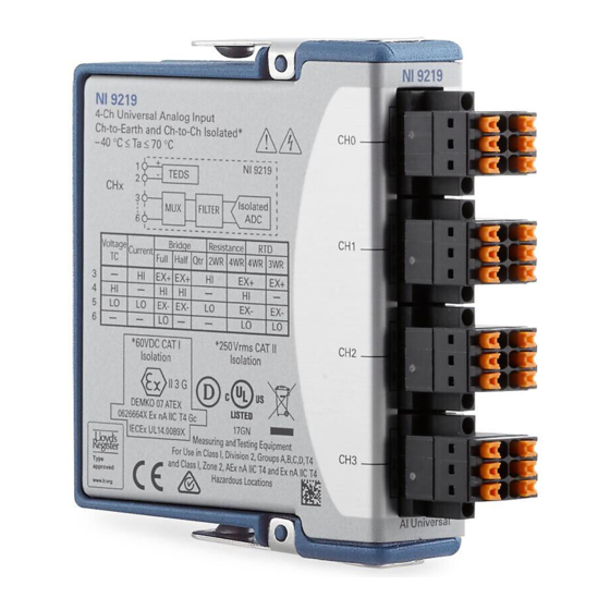
National Instruments NI-9219 Getting Started
Hide thumbs
Also See for NI-9219:
- Calibration procedure (50 pages) ,
- Getting started manual (40 pages) ,
- Operating instructions manual (36 pages)
Table of Contents
Advertisement
Quick Links
Advertisement
Table of Contents

Subscribe to Our Youtube Channel
Summary of Contents for National Instruments NI-9219
- Page 1 NI-9219 Getting Started 2022-07-06...
-
Page 2: Table Of Contents
Safety Guidelines for Hazardous Voltages....... . . 4 NI-9219 Safety Voltages (Black Connector)....... . . 5 Safety Guidelines for Hazardous Locations. - Page 3 NI-9219 Getting Started Open Contact Pinout........... 18 Where to Go Next.
-
Page 4: Overview
Note The guidelines in this document are specific to the NI-9219. The other components in the system might not meet the same safety ratings. Refer to the documentation for each component in the system to determine the safety and EMC ratings for the entire system. -
Page 5: Ni-9219 Safety Voltages (Black Connector)
Caution You must use the connector backshell kit to ensure that the terminals are not accessible. NI-9219 Safety Voltages (Black Connector) Connect only voltages that are within the following limits. Channel-to-channel © National Instruments... -
Page 6: Safety Guidelines For Hazardous Locations
60 V DC, Measurement Category I Safety Guidelines for Hazardous Locations The NI-9219 is suitable for use in hazardous locations; , and hazardous locations; and nonhazardous locations only. Follow these guidelines if you are installing the NI-9219 in a potentially explosive environment. Not following these guidelines may result in serious injury or death. -
Page 7: Electromagnetic Compatibility Guidelines
Each NI-9219 is marked and is suitable for use in Zone 2 hazardous locations, in ambient temperatures of -40 °C ≤ Ta ≤ 70 °C. If you are using the NI-9219 in Gas Group IIC hazardous locations, you must use the device in an NI chassis that has been evaluated as Ex nC IIC T4, Ex IIC T4, Ex nA IIC T4, or Ex nL IIC T4 equipment. -
Page 8: Special Conditions For Marine Applications
EMC performance is attained. Preparing the Environment Ensure that the environment in which you are using the NI-9219 meets the following specifications. Operating temperature (IEC 60068-2-1, IEC 60068-2-2) -40 °C to 70 °C... -
Page 9: Ni 9219 Pinout
NI-9219 Getting Started NI 9219 Pinout Mode Voltage — — Current — — 4-Wire Resistance 2-Wire Resistance — — Thermocouple — — 4-Wire RTD 3-Wire RTD — Quarter-Bridge — — Half-Bridge — Full-Bridge — — Open Contact — — Table 1. Signals by Mode... -
Page 10: Measurement Types
Negative sensor excitation connection Positive input signal connection Negative input signal connection TEDS data connection TEDS COM connection Table 2. Signal Descriptions Measurement Types The NI-9219 provides modes for the following measurement types. Voltage ■ Current ■ 4-Wire Resistance ■... -
Page 11: Current Connections
Minimize adjacent heat sources and air flow across the terminals. ■ Keep the ambient temperature as stable as possible. ■ Make sure the NI-9219 terminals are facing forward or upward. ■ Keep the NI-9219 in a stable and consistent orientation. ■... -
Page 12: 4-Wire Resistance And 4-Wire Rtd Connections
NI-9219 Getting Started Allow the thermal gradients to settle after a change in system power or in ■ ambient temperature. A change in system power can happen when the system powers on, the system comes out of sleep mode, or you insert/remove modules. -
Page 13: Half-Bridge Connections
NI-9219 Getting Started wire wire NI 9219 Related reference Full-Bridge Pinout ■ Half-Bridge Connections wire wire NI 9219 Related reference Half-Bridge Pinout ■ Digital In Connections – NI 9219 The digital in measurement type is only supported in CompactRIO systems. -
Page 14: Open Contact Connections
For more information about TEDS, visit ni.com/info and enter the Info Code rdteds. NI-9219 Connection Guidelines Make sure that devices you connect to the NI-9219 are compatible with the ■ module specifications. Use shielded cables and twisted pair wiring for the best signal quality. -
Page 15: Connecting To A Spring-Terminal Connector
– Signal NI 9219 Source You can connect floating signal sources to the NI-9219. Ensure that the ■ voltages on the HI and LO connections are within the channel-to-earth working voltage range. The following figure illustrates a floating connection for a voltage source. -
Page 16: High-Vibration Application Connections
NI-9219. Excitation Protection The NI-9219 protects the excitation circuit from overcurrent and overvoltage fault conditions. The NI-9219 automatically disables the circuit in the event of a fault condition. Whenever possible, channels automatically recover after the fault is removed. -
Page 17: Current Pinout
NI-9219 Getting Started Voltage Connections ■ Current Pinout — — — — Related reference Current Connections ■ Thermocouple Pinout — — — — Related reference Thermocouple Connections ■ 4-Wire Resistance and 4-Wire RTD Pinout — — Related reference 4-Wire Resistance and 4-Wire RTD Connections ■... -
Page 18: Full-Bridge Pinout
NI-9219 Getting Started 3-Wire RTD Connections ■ Full-Bridge Pinout — — Related reference Full-Bridge Connections ■ Half-Bridge Pinout — — — Related reference Half-Bridge Connections ■ Digital In Pinout — — — — Related reference Digital In Connections ■ Open Contact Pinout —... - Page 19 NI product. Product registration facilitates technical support and ensures that you receive important information updates from NI corporate headquarters is located at 11500 N Mopac Expwy, Austin, TX, 78759-3504, USA. © National Instruments © 2022 National Instruments Corporation.


Need help?
Do you have a question about the NI-9219 and is the answer not in the manual?
Questions and answers