
Subscribe to Our Youtube Channel
Related Manuals for Technische Alternative RAS PLUS DL


Summary of Contents for Technische Alternative RAS PLUS DL
- Page 1 www.ta.co.at RAS+DL Room sensor with remote display Version 2.03 Operation Programming Installation Instructions English...
-
Page 3: Table Of Contents
Table of Contents Version 2.03 Function description ................... 4 Programming manual ..................5 Menu – general overviews ....................6 Menu overview UVR16x2, RSM610, CAN-I/O45 and UVR1611 ......... 6 Menu overview for ESR21 (from version 5.0) and ESR31, UVR61-3 (from version 8.3), UVR63 (from version 1.5) .................... -
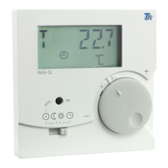
Page 4: Function Description
Function description The room sensor RAS+DL was specially developed for Technical Alternative control units and is intended for mounting in the living area (reference space). The room sensor should not be installed near a source of heat or near a window. It is only suitable for operation in dry rooms. The RAS+DL transmits the room temperature, relative room humidity, ambient air pressure, absolute humidity and the dew point as well as the operating mode and the correction factor for the set value (+/- 4 K) to the controller via the bidirectional data link (DL-bus). -
Page 5: Programming Manual
Programming manual Only the basic values are displayed in the factory settings of the room sensor: Room temperature Relative Room humidity Ambient air pressure Dewpoint Nominal value adjustment (+/- 4K) With the aid of programming, other values can be displayed. Access to the programming level is only possible from the "Standby"... -
Page 6: Menu - General Overviews
Menu – general overviews The displayed menu options are matched to the respective controller types: Menu overview UVR16x2, RSM610, CAN-I/O45 and UVR1611 In the menu section "CONFIG" gen- eral sensor settings are adjusted. The selection of the values and sym- bols to be displayed takes place in the menu section "VALUES". -
Page 7: Menu Overview For Esr21 (From Version 5.0) And Esr31, Uvr61-3 (From Version 8.3), Uvr63 (From Version 1.5)
Menu overview for ESR21 (from version 5.0) and ESR31, UVR61-3 (from version 8.3), UVR63 (from version 1.5) In the menu section "CONFIG" gen- eral sensor settings are adjusted. The selection of the values and sym- bols to be displayed takes place in the menu section "VALUES". -
Page 8: Menu Overview For All Other Controllers
Menu overview for all other controllers In the menu section "CONFIG" gen- eral sensor settings are adjusted. The selection of the values and sym- bols to be displayed takes place in the menu section "VALUES". The menu option "POWER" (heat quantity counter) is only displayed with those controllers that have this function. -
Page 9: Menu Config
Menu CONFIG The following settings are made here: Language selection SPR DE / LAN EN Time interval for continuing display TIME N Time before jumping back to the 1st display TIME R Address in the DL-bus network DL ADR ... -
Page 10: Time Before Jumping Back To The 1St Display Time B
Time before jumping back to the 1st display TIME R Entry 0 = There is no jumping back to the display of the 1st value. Factory setting: 0 After a long key press "0" flashes Selection of the desired time via a short key press. Confirmation of the desired time via a long key press. -
Page 11: Index Specification
Index specification To process sensor values in the controller, specification and selection of the sensor address (1-8) and the index (1-11) is necessary. Indices can be selected for the following values: Index Value Room temperature with offset values for +/- adjustment and the DIP switch (for evaluating "RAS"... -
Page 12: Entry Of An Offset Value For Sensor Correction Offset
A still unused network input variable must be selected for each new value. The values of the indices 1 and 5 displayed at the network input do not correspond to the temperatures and are only correctly displayed in the controller in the measured values overview and in the func- tions. -
Page 13: Display Of Operating Mode Symbols Symb
Example: If an offset value of 0.7K is set and a temperature of 21.0°C is measured, 21.7°C is indicated (index values 1 and 2). This corrected value is used in the sequence for all calcula- tions and forwarded to the controller. Among those controllers that have no bidirectional data link (e.g. -
Page 14: Menu Values
Menu VALUES This is where the display is selected: Sensor values SENSOR Output statuses OUTPUT Speed stages SPEED (only UVR16x2, RSM610, CAN-I/O45 and UVR 1611) Heat quantity counter POWER (only for controllers with a heat quantity counter) ... - Page 15 Menu output statuses OUTPUT Access the menu via a long key press. Selection via a long key press on the rele- vant output. The selection is indicated by a star symbol. Depending on the controller type, up to 14 output statuses can be displayed. Analogue outputs 15 and 16 of controllers UVR16x2 and UVR1611 cannot be dis- played.
-
Page 16: Menu Speed Stages Speed (Only Uvr1611)
Menu speed stages SPEED (only UVR1611) Access the menu via a long key press. Selection via a long key press on the rele- vant output. The selection is indicated by a star. The speed of this output is displayed after all the other displays have been dis- played. -
Page 17: Menu Heat Quantity Counter Power
Menu heat quantity counter POWER This menu option is only displayed for controllers with a heat quantity counter. Access the menu via a long key press. Selection via a long key press of the value of the respective heat quantity counter. The selection is indicated by a star. -
Page 18: Menu External Sensors Netw (Only Esr21 (From Version 5.0), Esr31, Uvr61-3 (From Version 8.3), Uvr63 (From Version 1.5))
Menu external sensors NETW (only ESR21 (from version 5.0), ESR31, UVR61-3 (from version 8.3), UVR63 (from version 1.5)) This selection is only possible for the controllers listed above, as only these controllers can display external sensors via the data link. Access the menu via a long key press. -
Page 19: Menu Analogue Can Network Inputs Analnw (Only Uvr1611)
Menu analogue CAN network inputs ANALNW (only UVR1611) This selection is only possible for the controller UVR1611. For output 14, the query NETW.IP.=>DL.: must be set to " ". Access the menu via a long key press. Selection via a long key press t the relevant analogue network input. -
Page 20: Menu Digital Can Network Inputs Diginw (Only Uvr1611)
Menu digital CAN network inputs DIGINW (only UVR1611) This selection is only possible for the controller UVR1611. For output 14, the query NETW.IP.=>DL.: must be set to " ". Access the menu via a long key press. Selection via a long key press at the rele- vant digital network input. -
Page 21: Menu Symbol Allocation Symb
Menu symbol allocation SYMB This menu allows for allocation of a symbol (or several symbols) to display values. However, each symbol can only be allocated once. The following symbols can be allocated: Example: The symbol "Burner" is to be allocated to the output O5: Access the menu via a long key press. - Page 22 A long key press confirms the allocation of the "Burner" symbol to output O5. Flashing of the symbol stops. Scroll forward to the next symbol to be allocated or ..exit the menu by scrolling forward to "EXIT" If the symbol is allocated to an Output or a Digital CAN network input (UVR1611), then it is shown in each display view for as long as the output or the digital network input is set to "ON".
-
Page 23: Deleting Or Changing A Symbol Allocation
Deleting or changing a symbol allocation: Example: Deleting or changing the "Burner" symbol allocation to output O5: Access the menu via a long key press. By scrolling forwards with short key presses, the desired "burn- er" symbol appears in the display. A long key press causes the allocation to be cleared. -
Page 24: Reset To Factory Setting
Reset to factory setting To reset the sensor RAS+DL to its factory settings, the key must be pressed during insertion of the data link into the sensor: The "RESET" display appears briefly Then the menu language is selected (DE = German, EN = English), the tool symbol flashes A long key press causes the language to be... -
Page 25: Operation
Operation Room sensor with UVR16x2, RSM610, CAN-I/O45, UVR1611 (from vers. A3.00 and serial number 13286) or with UVR63-H (from vers. 7.2) Pressing the Key causes the next value to be displayed. The basic display values are dis- played in the following sequence. Then the pre-programmed values become visible. If there are outputs that are combined with a symbol, then the symbol is also displayed. -
Page 26: Use As A Remote Control
The signal reported at the controller corresponds to the room temperature changed using the rotary knob. The following signals are forwarded to the controller according to the switch setting: • Automatic mode = Room temperature +/- inverse rotary knob • Normal mode = Room temperature + 50°C +/- inverse rotary knob •... -
Page 27: Electrical Connections
Electrical connections The sensor is connected to both DL connections. The polarity of DL and GND on the control- ler is reversible. Alternatively, the 12 V connection can be used for the power supply to re- lieve the load on the DL bus. Otherwise, the sensor is supplied with power via the DL bus. Any cable with a cross section of 0.75 mm²... - Page 28 1. The company Technische Alternative RT GmbH provides a two-year guarantee from the date of purchase by the end consumer for all the devices and parts which it sells. Defects must be reported immediately upon detection and within the guarantee period.
Need help?
Do you have a question about the RAS PLUS DL and is the answer not in the manual?
Questions and answers