Table of Contents
Advertisement
Advertisement
Table of Contents
Troubleshooting

Related Manuals for SKF TKSA 31


Summary of Contents for SKF TKSA 31
- Page 1 SKF TKSA 31 & TKSA 41 Instructions for use...
-
Page 3: Table Of Contents
6.4 Soft foot 2 ..............36 2.3 Connecting the wireless MU on TKSA 41 ..... 10 Settings .............. 37 2.4 Connecting the wired MU on TKSA 31/41 ... 11 7.1 Main settings menu ..........37 2.5 Adjusting the lasers ..........12 7.2 User settings ............ -
Page 4: Ec Declaration Of Conformity
EC Declaration of conformity We, SKF Maintenance Products, Kelvinbaan 16, 3439 MT Nieuwegein, The Netherlands herewith declare that the following products: SKF Shaft Alignment Tool TKSA 31 & TKSA 41 has been designed and manufactured in accordance with: EMC DIRECTIVE 2004/108/EC as outlined in the harmonized norm for EN 61326-1:2013 Electrical equipment for measurement, control and laboratory use –... -
Page 5: Safety Recommendations
You can be seriously injured; equipment and data can be damaged if you do not follow the safety warnings. • TKSA 31/41 uses Class 2 lasers with output power < 1.0mW. Never stare directly into the laser beam. Never direct the laser into anyone else’s eyes. •... -
Page 6: Introduction
In essence, the objective is to have a straight line through the centres of all of the shafts of the machines. The SKF Shaft Alignment Tool TKSA 31/41 is a laser shaft alignment tool that allows an easy and accurate method for aligning the shafts of a driving machine (eg electric motor) and a driven machine (eg. -
Page 7: Principle Of Operation
1.2 Principle of operation The TKSA 31/41 uses two measuring units (MU) both provided with a laser diode and a CCD detector. As the shafts are rotated through 180° any parallel or angular misalignment causes the two laser lines to defl... -
Page 8: Case Content
1.3 Case content 1. 1 × TKSA 31/41 Display unit 8. 1 × 12V DC 3A Power supply 2. 1 × TKSA 31/41 S Measuring unit 9. Country adapters (US, UK, EU, AUS) 3. 1 × TKSA 31/41 M Measuring unit 10. -
Page 9: Product Description
• Red Line laser • 2 × threaded 150 mm rods per V-bracket • Multiple positions for chain nut • Large Resistive colour touchscreen • Rugged Design • Screen orientation fl ip function (TKSA 41) SKF TKSA 31 & TKSA 41... -
Page 10: Getting Started
Make sure the rods are firmly tightened to the brackets before mounting the measuring units. Make sure the measuring units are firmly tightened on the rods and DO NOT lie on bracket. Brackets are symmetric, they can be mounted either way. SKF TKSA 31 & TKSA 41... -
Page 11: Switching On The Display Unit
The DU will enter deep sleep after 2 hours of inactivity. • The DU will never turn off during an alignment job. • The Display Unit does NOT need to be switched off. Short press for stand-by only. SKF TKSA 31 & TKSA 41... -
Page 12: Connecting The Wireless Mu On Tksa 41
Once connected, the MU LED remains off. • If the MUs do not connect, check the Troubleshooting section. • Switch off the MU with a long press on the On/Off button until a steady red LED appears. SKF TKSA 31 & TKSA 41... -
Page 13: Connecting The Wired Mu On Tksa 31/41
2.4 Connecting the wired MU on TKSA 31/41 The MU can be connected to the DU via USB cable. • Make sure the MU are both switched off. (TKSA 41 only). • Connect the USB cables to the Display Unit. -
Page 14: Adjusting The Lasers
• Lock firmly the “S” unit in position. • Use the knob on top of the “M” unit to vertically adjust the laser position on the “S” unit. SKF TKSA 31 & TKSA 41... -
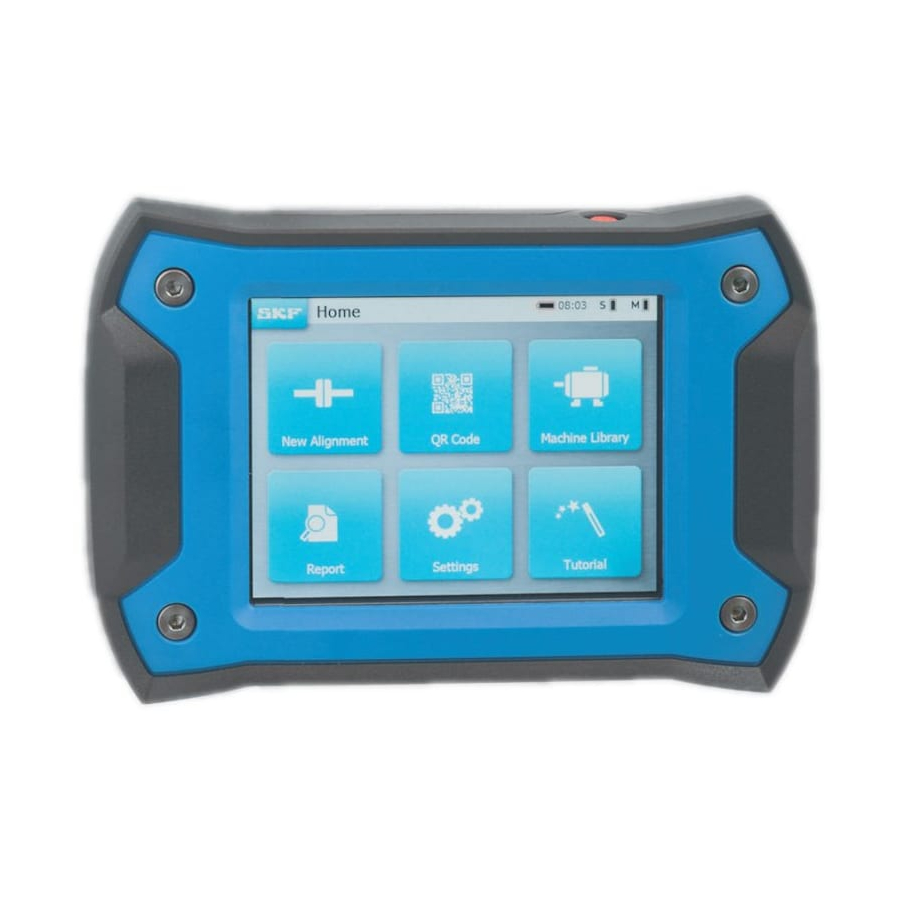
Page 15: Home Screen
Scan a QR code to recognize SKF Menu an existing machine or create a new machine Start a new Open the alignment job machine library, check previous alignments and start new ones Open Reports Open Settings Open Help SKF TKSA 31 & TKSA 41... -
Page 16: Charging
The display unit will wake up when connected to power. 2.8 Charging the measuring units • Connect the MU to the display unit with the micro USB cables. • The charging symbol will be shown on the screen. SKF TKSA 31 & TKSA 41... -
Page 17: Take A Measurement
3. Take a measurement 3.1 3 Ways to start an alignment From the Home screen: Click on “New alignment” Click on “QR code” Click on “Machine library” SKF TKSA 31 & TKSA 41... -
Page 18: Dimensions Screen
Fill in the angular and parallel misalignment and click on the corresponding blue button. • The units English or Metric can be selected from the settings menu before the alignment is started. • Go to the measurement screen by clicking on the next arrow. SKF TKSA 31 & TKSA 41... -
Page 19: Measurements
Do not use the measuring equipment as a handle to turn the shafts. • Make sure the motor bolts are tightened before starting the measurements. • The alignment job can be cancelled at any time. SKF --> End Alignment SKF TKSA 31 & TKSA 41... -
Page 20: Measurements 17
The raw S and M reading in the bottom left of the screen can be enabled from Settings --> General. • The angle difference between the S and M MU should be less than 2°. SKF TKSA 31 & TKSA 41... -
Page 21: Automatic Measurements
Turn the MU in the right position and the measurement will be taken automatically. • Once the first measurement is taken, move on with the other measurements. • Should the MU move during countdown, the measurement will be interrupted. SKF TKSA 31 & TKSA 41... -
Page 22: Free Measurement (Tksa 41 Only)
Free measurement can be enabled from Settings --> Measurement Settings. • Automatic measurement cannot be used together with free measurements. • Better results are achieved when the total measurement angle is close to 180°. Measurement 1 Measurement 2 Measurement 3 SKF TKSA 31 & TKSA 41... -
Page 23: Backlash
Backlash warnings are enabled only when the MU are within a blue wedge. • It is always possible to take a measurement with backlash (ie MU angle >2°). - Accept the warning message to take the measurement anyway. SKF TKSA 31 & TKSA 41... -
Page 24: Correct The Alignment
Correction Graphical view Within tolerance Close to tolerance Symbol Out of tolerance Take measurements again Change Finish and Create report tolerance The black shafts icons are fixed and do not represent the alignment state. SKF TKSA 31 & TKSA 41... -
Page 25: Vertical Correction - Side View - Shimming
Make sure all motor feet are shimmed. • Only coupling values matter. Once they are within chosen tolerance do not try to overcorrect and do not try to reach zero for the feet value. SKF TKSA 31 & TKSA 41... - Page 26 Vertical correction – Side view – Shimming Angular Target line misalignment Parallel /offset Feet values This motor has to go down! SKF TKSA 31 & TKSA 41...
-
Page 27: Horizontal Correction - Top View
STOP when the coupling values are within tolerance and both Green marks are shown. IMPORTANT: • Start by moving the motor side with the highest correction value. • Tighten the bolts when finished with the horizontal correction. SKF TKSA 31 & TKSA 41... - Page 28 Horizontal correction – Top view Angular Perfect / target line misalignment Parallel /offset Feet values SKF TKSA 31 & TKSA 41...
-
Page 29: Recheck - Remeasure
• Perform the three measurements. • Check the result screen: 1. Click the shim button to correct 2. Click the flag button to end the the alignment. alignment and create a report. SKF TKSA 31 & TKSA 41... -
Page 30: Create A Report
Reports can be found on the folder “Alignment reports” on the USB stick. PDF reports files are named using the report name and the date. If the USB icon does not become active, use another USB stick. SKF TKSA 31 & TKSA 41... -
Page 31: Report Creation Page
Operator: Filled automatically with user data. • Photo: Up to 3x photos can be added to the report (TKSA 41 only) - Photos can also be taken during the alignment via SKF --> Photo notes • Comments: Comments can be added. -
Page 32: Report Content And Browser
The report additionally contains: • User name, address and logo when filled in. • Dimensions, alignment and correction results, soft foot results • Instrument information. • Machine name, QR code. • Space for date and signature. SKF TKSA 31 & TKSA 41... - Page 33 SKF TKSA 31 & TKSA 41...
-
Page 34: Qr Codes, Machine Library, Soft Foot
The machine can also be selected directly from the machine library. Note: Additional QR code stickers are available from SKF. Any QR code version 2 can be recognized by the display unit (Up to 20 characters in the QR code). -
Page 35: Machine Library
Seeing the alignment jobs performed on a machine including dates. • Checking whether the machine has been aligned within tolerance. • Attribute a QR code and a picture to a machine. • Start a new alignment for a given machine. SKF TKSA 31 & TKSA 41... - Page 36 Machine library – browsing and gestures Swiping with one finger and clicking can be used in the machine library. Columns can be sorted by machine name, operator or alignment date. Green = Clicking area = Swiping area SKF TKSA 31 & TKSA 41...
-
Page 37: Soft Foot 1
Chose the tolerance by clicking on the tolerance button. Measuring soft foot: 1. Loosen the bolt of the foot and click OK. 2. Tighten the bolt of the foot and click OK. 3. Repeat for all 4 × feet. SKF TKSA 31 & TKSA 41... -
Page 38: Soft Foot 2
5. Click on check or click the next button to leave the soft foot function. 6. Remeasure soft foot and click next to leave the function. Note: SKF high precision machinery shims, search for “TMAS” on SKF.com SKF TKSA 31 & TKSA 41... -
Page 39: Settings
Adjust the screen brightness by clicking the left or right sun icon or by sliding the brightness bar with a swiping gesture. All default: All default will reset all settings to their default values including the user preferences. SKF TKSA 31 & TKSA 41... -
Page 40: User Settings
Load the file on the root of a USB stick. • When the USB stick is plugged to the display unit, the plus button becomes blue. • Click “plus” to import the company logo. • Click ‘minus” to delete the logo. SKF TKSA 31 & TKSA 41... -
Page 41: Measurements Settings
The “ask” option means a popup window will give the choice to the user. “Auto measurement” is available when “Free measurement” is off. Note: We recommend always verifying the alignment correction previously made. See chapter 3 for more details on the measurement options. SKF TKSA 31 & TKSA 41... -
Page 42: Display Unit And Measuring Unit Info
Visualize the live internal temperature, live angles and live detector reading (position) of the S and M measuring units. • Update the measuring units firmware. • Find existing or pair new measuring units --> Find measuring units. SKF TKSA 31 & TKSA 41... -
Page 43: Languages
7.5 Languages The following languages are available: English, French, German, Spanish, Italian, Portuguese, Russian and Simplified Chinese. SKF TKSA 31 & TKSA 41... -
Page 44: Units And Date & Clock
Units allows the user to choose between imperial (inches) and metric units (meters). Note: Units cannot be changed when an alignment job is started. Date & clock allows setting the date and time. These will be shown on the reports. SKF TKSA 31 & TKSA 41... -
Page 45: General Settings
Confirm delete: Ask confirmation when a report or machine is being deleted. S and M readings: S and M measuring units live detector readings are displayed during the measurements when this option is enabled. SKF TKSA 31 & TKSA 41... -
Page 46: Troubleshooting
If the problem remains, measure the output voltage of the power adapter with a Voltmeter set on DC Voltage. • If the Voltmeter shows a value around +/- 12V, the power adapter is okay. • If the Voltmeter shows 0, replace the power adapter. SKF TKSA 31 & TKSA 41... -
Page 47: Firmware Update
8.4 Firmware update The latest version of the firmware can be found on SKF.com Display unit firmware update • Load the file “firmware.pac” on a USB stick (at the root folder). • Plug the USB stick to the display unit while DU is switched on. -
Page 48: Wireless Connection Troubleshooting
- Validate with the “OK” button - A Bluetooth symbol will appear next to the S and M letters - Both MU will now connect to the DU and data will be populated in the MU info menu. SKF TKSA 31 & TKSA 41... -
Page 49: Technical Specifications
9. Technical specifications Technical data Designation TKSA 31 TKSA 41 Description SKF Shaft Alignment Tool TKSA 31 SKF Shaft Alignment Tool TKSA 41 Measuring unit(s) TKSA 31 TKSA 41 Sensors & 29 mm (1.1 in.) CCD with red line laser 29 mm (1.1 in.) CCD with red line laser... - Page 50 Live values for vertical and horizontal Live values for vertical and horizontal Soft foot correction Laser soft foot Laser soft foot Extra features Screen orientation flip QR code readering, screen orientation flip Machine view Fixed angle Fixed angle SKF TKSA 31 & TKSA 41...
- Page 51 -20 °C to +70 °C (-4 °F to +158 °F) -20 °C to +70 °C (-4 °F to +158 °F) Relative humidity 10% to 90% non condensing 10% to 90% non condensing IP rating IP 54 IP 54 SKF TKSA 31 & TKSA 41...
- Page 52 +1 year upon registration In the case TKSA 31 TKSA 41 2 × TKSA 31 measuring unit 2 × TKSA 41 measuring unit 1 × TKSA 31 display unit 1 × TKSA 41 display unit 2 × Shaft brackets with chains 2 ×...
- Page 53 2 × Sliding wheels for non-rotating shafts to be mounted on standard V-bracket (No bracket supplied) for TKSA 31/41/60/80 TKSA MAGBASE 2 × Magnetic bases for use with offset brackets only for TKSA 31/41/60/80 TKSA EXT50 2 × 50 mm (2 in.) offset brackets compatible with standard and magnetic V-brackets...
- Page 54 SKF TKSA 31 & TKSA 41...
- Page 56 SKF Maintenance Products ® SKF is a registered trademark of the SKF Group. © SKF Group 2015/11 www.mapro.skf.com www.skf.com/mount...
Need help?
Do you have a question about the TKSA 31 and is the answer not in the manual?
Questions and answers