Table of Contents
Advertisement
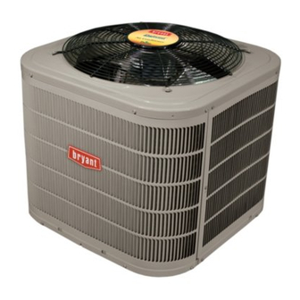
180CNV EVOLUTION
VARIABLE SPEED HEAT PUMP
WITH PURONr REFRIGERANT
(2 - - 5 Ton)
NOTE: Read the entire instruction manual before starting the installation.
TABLE OF CONTENTS
. . . . . . . . . . . . . . . . . . . . . . . . . . . . . .
. . . . . . . . . . . . . . . . . . . . . . . . .
. . . . . . . . . . . . . . . . . . . . . . . . . . .
. . . . . . . . . . . . . . . . . . . . . . . . .
. . . . . . . . . . . . . . . . . . . . . . . . .
. . . . . . . . . . . . . . . . . . . . . . . . . . .
. . . . . . . . . . . . . . . . . . . . . . . . . . . . . . .
R
EXTREME SERIES
Installation Instructions
PAGE NO.
. . . . . . . . . . . . . . . . . . . .
. . . . . . . . . .
3- -9
. . . . . . . . . . .
. . . . . . . . . . . . . . . . . . .
. . . . . . . . . . . . . . . .
. . . . . . . . . . . . . . . . . . .
. . . . . . . . . . . .
. . . . . . . . . . . .
. . . . . . . . . . .
. . . . . . . . . . . . . . . . . . . .
.
. . . . . . . . . . . . . . . . . . . . . . .
15
. . . . . . . . . . . . . . . . . . . .
15
. . . .
15
Information in these installation instructions pertains only to
180CNV series units.
Indoor Thermostat Control Options
1
Model
2
180CNV
3
3
* Requires model SYSTXBBITW01 ---A, SYSTXBBITC01 ---A, SYS-
3
TXBBTC01 ---B or newer. Ensure the wall control software has been updat-
ed to the latest version available from HVAC Partners.
4
4
SAFETY CONSIDERATIONS
4
Improper installation, adjustment, alteration, service, maintenance,
5
or use can cause explosion, fire, electrical shock, or other
6
conditions which may cause death, personal injury, or property
6
damage. Consult a qualified installer, service agency, or your
6
distributor or branch for information or assistance. The qualified
installer or agency must use factory- -authorized kits or accessories
7
when modifying this product. Refer to the individual instructions
8
packaged with the kits or accessories when installing.
9
Follow all safety codes. Wear safety glasses, protective clothing,
9
and work gloves. Use quenching cloth for brazing operations.
9
Have fire extinguisher available. Read these instructions
thoroughly and follow all warnings or cautions included in
literature and attached to the unit. Consult local building codes and
current editions of the National Electrical Code ( NEC ) NFPA 70.
In Canada, refer to current editions of the Canadian electrical code
CSA 22.1.
Recognize safety information. This is the safety- -alert symbol
When you see this symbol on the unit and in instructions or
manuals, be alert to the potential for personal injury. Understand
these signal words; DANGER, WARNING, and CAUTION. These
words are used with the safety- -alert symbol. DANGER identifies
the most serious hazards which will result in severe personal injury
or death. WARNING signifies hazards which could result in
personal injury or death. CAUTION is used to identify unsafe
practices which would result in minor personal injury or product
and property damage. NOTE is used to highlight suggestions
which will result in enhanced installation, reliability, or operation.
!
CUT HAZARD
Failure to follow this caution may result in personal injury.
Sheet metal parts may have sharp edges or burrs. Use care and
wear appropriate protective clothing and gloves when
handling parts.
Evolution
Control
Yes*
CAUTION
! !
Advertisement
Table of Contents

Related Manuals for Bryant 180CNV024


Summary of Contents for Bryant 180CNV024
-
Page 1: Table Of Contents
180CNV EVOLUTION EXTREME SERIES VARIABLE SPEED HEAT PUMP WITH PURONr REFRIGERANT (2 - - 5 Ton) Installation Instructions NOTE: Read the entire instruction manual before starting the installation. TABLE OF CONTENTS Information in these installation instructions pertains only to 180CNV series units. PAGE NO. -
Page 2: Installation Recommendations
INSTALLATION RECOMMENDATIONS WARNING In some cases noise in the living area has been traced to gas pulsations from improper installation of equipment. EXPLOSION HAZARD 1. Locate unit away from windows, patios, decks, etc. where Failure to follow this warning could unit operation sound may disturb customer. -
Page 3: Installation
The outdoor unit contains the correct amount of refrigerant charge Step 2 — Install on a Solid, Level Mounting Pad for operation with AHRI rated and factory- -approved smallest If conditions or local codes require the unit be attached to pad, tie indoor unit when connected by 15 ft (4.57 m) of field- -supplied or down bolts should be used and fastened through knockouts factory accessory tubing. -
Page 4: Step 4 - Operating Ambient
Minimum Tube Diameter Diameter Diameter Diameter Diameter 180CNV024 180CNV036 180CNV048 1--- 1/8 180CNV060 1--- 1/8 * Units are rated with 25 ft. (7.6 m) of lineset. See Product Data sheet for performance data when using different size and length line sets. -
Page 5: Step 7 - Make Electrical Connections
Outdoor Unit Connected to Factory- - Approved Indoor Evacuate Refrigerant Tubing and Indoor Coil Unit CAUTION Outdoor unit contains correct system refrigerant charge for operation with factory- -approved, AHRI- -rated smallest indoor unit when connected by 15 ft. (4.57 m) of field- -supplied or UNIT DAMAGE HAZARD factory- -accessory tubing, and factory- -supplied filter drier. -
Page 6: Step 8 - Compressor Crankcase Heater
External to the unit, the same accessories such as support feet, snow rack, wind baffle etc., FIELD POWER are available on other Bryant units can also be used on this line of WIRING product. Refer to the individual Installation Instructions packaged with kits or accessories when installing. -
Page 7: Step 11 - System Functions And Seq. Of Operation
CAUTION ENVIRONMENTAL HAZARD Failure to follow this caution may result in environmental damage. Federal regulations require that you do not vent refrigerant to the atmosphere. Recover during system repair or final unit disposal. Follow these steps to properly start up the system: 1. -
Page 8: Step 12 - Check Charge
Outdoor Fan Motor Operation The outdoor unit control (Fig. 9) energizes outdoor fan anytime compressor is operating as needed during low- -ambient cooling operation. The outdoor fan remains energized if a pressure switch opens or compressor scroll over temperature should occur. This OD fan is an ECM motor which operates at varying speeds depending on the ambient and the demand. -
Page 9: Step 13 - Pumpdown
MODEL (K--- ohms) MODEL PLUG S Compressor speed NUMBER NUMBER S Contactor operation Pins 1--- 4 Pins 2--- 3 S Outdoor fan motor operation 180CNV024 HK70EZ011 5.1K 150K S Low ambient cooling 180CNV036 HK70EZ012 5.1K 180K S Crankcase heater operation... - Page 10 NOTE: The model plug takes priority over factory model Inverter Voltage Sensing information input at the factory. If the model plug is removed after The control board senses the presence or absence of 230 V through initial power up, the unit will operate according to the last valid the feedback from inverter.
- Page 11 This compressor operates with a 3- -phase variable frequency PWM variable voltage to the three fusite terminals. Table 5 – Variable Speed Compressor Resistances A170293 (winding resistance at 70_F 20_F) Fig. 12 - - Outdoor Coil Thermistor (OCT) Attachment 180CNV024 180CNV048 (On Distributor Tube) WINDING 180CNV036 180CNV060 Between terminals .681...
- Page 12 ECM Fan Motor If verification of proper operation is required for the ECM motor User Interface (UI) Furnace or Fan Coil VS AC used in this unit, follow these steps: C and D 1. Verify that the 230v input to the transformer is present. not required on VS air conditioner 2.
- Page 13 SEC2 SEC1 PWM2 PWM1 PL11 COMM STATUS LS Y UTIL FORCED A B C NO MODEL DEFROST Utility Interface* A11544 Fig. 16 - - Variable Speed Control Board with optional Utility Relay...
- Page 14 Table 7 – Troubleshooting...
-
Page 15: Final Checks
FINAL CHECKS CARE AND MAINTENANCE IMPORTANT: IMPORTANT: Before leaving job, be For continuing high performance and to minimize possible equipment failure, periodic maintenance must be sure to do the following: performed on this equipment. 1. Ensure that all wiring is routed away from tubing Frequency of maintenance may vary depending upon and sheet metal edges to prevent rub- -through or geographic areas, such as coastal applications. - Page 16 Catalog No. II180CNV ---01 E2017 Bryant Heating & Cooling Systems 7310 W. Morris St. Indianapolis, IN 46231 Edition Date: 12/17 Manufacturer reserves the right to discontinue, or change at any time, specifications or designs without notice and without incurring obligations.
Need help?
Do you have a question about the 180CNV024 and is the answer not in the manual?
Questions and answers