Bryant 650A Service Manual
13 seer heat pump with puron refrigerant
Hide thumbs
Also See for 650A:
- User manual (21 pages) ,
- Installation and start-up instructions manual (12 pages)
Table of Contents
Advertisement
13 SEER
HEAT PUMP WITH
PURON® REFRIGERANT
TM
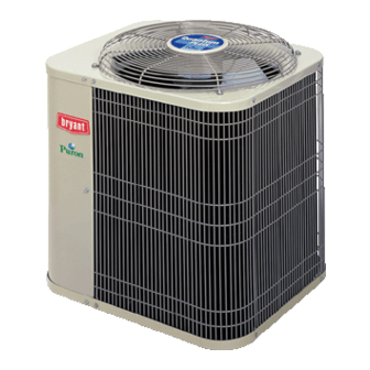
The Model 650A 13 SEER heat pump (with efficiencies up to 14.5
SEER) is designed for operation with Puron® refrigerant. Home-
owners will appreciate the 650A because of it's efficiency, envi-
ronmental soundness, and Puron's availability for years to come.
Another benefit of the 650A is the durability of the scroll compres-
sor. Model 650A has received certifications from UL (U.S. and
Canada), ARI, and CEC. The 650A is also approved by Energy
®
Star
for energy efficiency.
AVAILABLE OPTIONS
REFRIGERANT —The environmentally sound refrigerant used
in the 650A is Puron. This advanced refrigerant contains no
chlorine which can contribute to ozone depletion in the atmo-
sphere, so it's a smart choice for homeowners who are con-
cerned with protecting our environment, now and for future
generations. And it's a smart choice for anyone interested in
high-efficiency cooling.
BRYANT'S EVOLUTION™ CONTROLS —These industry-
leading controls, when installed with Bryant's Perfect Humidity™
variable-speed furnaces or fan coils, provide the homeowner
with:
–unparalleled control of temperature, humidity, indoor air quality,
and zoning
–unprecedented ease of use
–simple operation through on-screen, text-based service
reminders
Optional remote access through telephone or Internet is also
available when combined with a remote connectivity kit.
RELIABLE BUILT-IN COMPONENTS —All units include a suc-
tion line accumulator that minimizes the amount of liquid refrig-
erant that reaches the compressor; a high-pressure switch for
high-pressure protection; a low-pressure switch for loss of
charge protection; and a heavy duty, high filtration and moisture
removal liquid-line filter drier specially designed for Puron is
standard with every unit. A crankcase heater is standard on the
048 and 060 sizes.
COMPRESSOR
PROTECTION —Each
motor is protected with internal temperature and current-sensi-
tive overloads. For improved serviceability all models are
equipped with a compressor terminal plug.
UNIT DESIGN —Copper tube, enhanced aluminum fin coil is
designed for strong heat transfer. Vertical air discharge carries
sound and hot condenser air up and away from adjacent patio
areas and foliage. Heat pump style base pan is popular for its
easy removal of water, dirt, and leaves.
The AeroQuiet System (AQS) consists of 4 design features to
achieve ultra-low sound ratings.
Aerocoustic Design featuring the AeroMax™ opening and wire
dome top results in quieter and more efficient operation.
Energy-Efficient Fan and Fan Motor provide a slower fan
operation, thus reducing noise and improving efficiency.
Sound Hood muffles noise from operation.
Discharge Muffler minimizes low frequency sound and pres-
sure pulsation generated by compressor discharge gas.
WEATHER-PROTECTIVE CABINET —The casing steel is galva-
nized and coated with a layer of zinc phosphate. A layer of modified
polyester powder is then applied and baked on, providing each unit
with a durable finish that will last for many years.
All screws on cabinet exterior are coated for a long-lasting, rust-
resistant, quality appearance.
HEAVY DUTY INLET GRILLE —The DuraGuard™ coil protector,
made of a coated steel wire grid with vertical 3/8-in. spacing, is
designed to help protect the coil from inclement weather, vandal-
ism, and incidental damage. It provides protection while not restrict-
ing airflow and maintaining ease of coil inspection and cleaning.
EASY SERVICEABILITY —One access panel provides access
to electrical controls and compressor. Removal of wire dome
gives access to fan motor and removal of the top gives access to
the coil.
WIDE RANGE OF SIZES —Available in 6 nominal sizes from
024 through 060 to meet the needs of residential and light com-
mercial applications.
LIMITED WARRANTY —Standard 5-year limited warranty on all
parts, with 10-year limited warranty on compressor.
TOTALLY ENCLOSED FAN MOTOR —Means greater reliability
under adverse weather conditions and dependable performance
for many years. Permanent split-capacitor-type motors provide
more economical operation.
DEFROST CONTROL BOARD —Incorporates a built-in 5-
minute compressor time-delay relay, defrost relay, defrost timer,
and low-voltage terminal board. The defrost control is a time/tem-
perature initiation/termination control, which includes 4 field-
selectable (DIP switch) time periods of 30, 60, 90, and 120 min-
utes. This control also includes a field-selectable (DIP switch)
Quiet Shift defrost mode which, if selected, maintains extremely
quiet operation during defrost.
APPLICATION VERSATILITY —The 650A can be combined
with a wide variety of evaporator coils and blower packages to
provide quiet, dependable comfort. The 650A can be installed
on a roof or at ground level on a slab.
EXTERNAL SERVICE VALVES —Both service valves are brass,
back seating type with sweat connections. Valves are externally
located so refrigerant tube connections can be made quickly
and easily. Each valve has a service port for ease of checking
operating refrigerant pressures.
THERMOSTATIC EXPANSION VALVE (TXV) —This unit must
be installed with a Puron® refrigerant approved TXV on the
indoor coil. The FX4 and FV4 fan coils and CK5P furnace coil
scroll
compressor
come factory equipped with Puron-refrigerant TXVs. When
installed with these fan coils, no further change is required.
For any other coil combination, the approved field accessory
Puron-refrigerant TXV must be installed. For applications with
fan coils such as the FC4 and FK4 which have R-22 TXVs, the
R-22 TXV must be replaced with the approved field accessory
Puron-refrigerant TXV.
ELECTRICAL RANGE —All units are offered in 208/230v single
phase only.
650A
Sizes 024 thru 060
Form No. PDS 650A.24.6
Advertisement
Table of Contents

Related Manuals for Bryant 650A


Summary of Contents for Bryant 650A
- Page 1 3/8-in. spacing, is designed to help protect the coil from inclement weather, vandal- The Model 650A 13 SEER heat pump (with efficiencies up to 14.5 ism, and incidental damage. It provides protection while not restrict- SEER) is designed for operation with Puron®...
- Page 2 DIMENSIONS —2—...
-
Page 3: Model Number Nomenclature
67.5 69.0 70.0 67.5 65.0 59.0 Note: Tested in accordance with ARI Standard 270-95. (Not listed with ARI). MODEL NUMBER NOMENCLATURE 650A Model Number Standard Unit 13 SEER Split-System Heat Pump Series Electrical Supply A – Original Series N – 208/230-1-60 B –... -
Page 4: Specifications
ISO 9001:2000 ® REGISTERED As an ENERGY STAR® CERTIFICATION APPLIES ONLY partner, Bryant Heating & WHEN THE COMPLETE SYSTEM Cooling Systems has IS LISTED WITH ARI. determined that this prod- uct meets the ENERGY STAR® guidelines for energy efficiency. *Refer to the combination ratings in the Product Data Sheet for system combinations that meet Energy Star® efficiency standards. - Page 5 SPECIFICATIONS Continued UNIT SIZE-SERIES 042-D, E 048-D, E, F 060-D, E Operating Weight (Lb) ELECTRICAL Unit Volts—Hertz—Phase 208/230—60—1 Operating Voltage Range* 187—253 Compressor Rated Load Amps 21.1 20.5/21.8 27.6 Compressor Locked Rotor Amps 104.0 109.0/117.0 158.0 Condenser Fan Motor—Full Load Amps Minimum Unit Ampacity for Wire Sizing 27.5 27.0/28.6...
- Page 6 ** Outdoor air temperature sensor is an accessory for all Bryant electronic thermostats, except the non-programmable air conditioner version and builder’s thermostats. It allows the temperature at a remote location (outdoors) to be displayed on the thermostat.
- Page 7 11. Outdoor Air Temperature Sensor Designed for use with Bryant Thermostats listed in this publication. This device enables the thermostat to display the outdoor temperature. This device also is required to enable special thermostat features such as auxiliary heat lock out .
- Page 8 ACCESSORY DESCRIPTION AND USAGE (continued) 15. Sound Hood Wraparound sound reducing cover for the compressor. Reduces the sound level by about 2 dBA. Usage Guideline: Suggested when unit is installed closer than 15 ft to quiet areas—bedrooms, etc. Suggested when unit is installed between two houses less than 10 ft apart. 16.
- Page 9 COMBINATION RATINGS ARI STANDARD RATINGS* Cooling Heating Seasonal Efficiency SEER Field-Supplied High-Temp Low-Temp Accessory‡ Factory- UNIT Supplied Puron SIZE- INDOOR Enhance- Standard Puron SERIES UNIT CFM†† ment Rating HSPF & TDR** *FX4BNF030 25,000 TDR&TXV 13.00 — — — 11.10 25,000 3.30 16,600 2.38...
-
Page 10: Combination Ratings Continued
COMBINATION RATINGS continued ARI STANDARD RATINGS* Cooling Heating Seasonal Efficiency SEER Field-Supplied High-Temp Low-Temp Accessory‡ Factory- UNIT Supplied Puron SIZE- INDOOR Enhance- Standard Puron SERIES UNIT CFM†† ment Rating & TDR** HSPF FV4BNF003 29,400 TDR&TXV 14.50 — — — 12.55 28,600 3.70 17,700... - Page 11 COMBINATION RATINGS continued ARI STANDARD RATINGS* Cooling Heating Seasonal Efficiency SEER Field-Supplied High-Temp Low-Temp Accessory‡ Factory- UNIT Supplied Puron SIZE- INDOOR Enhance- Standard Puron SERIES UNIT CFM†† ment Rating HSPF & TDR** FV4BNF003 34,000 TDR&TXV 14.00 — — — 11.75 35,200 3.54 22,200...
- Page 12 COMBINATION RATINGS continued ARI STANDARD RATINGS* Cooling Heating Seasonal Efficiency SEER Field-Supplied High-Temp Low-Temp Accessory‡ Factory- UNIT Supplied Puron SIZE- INDOOR Enhance- Standard Puron SERIES UNIT CFM†† ment Rating & TDR** HSPF COILS + 355MAV042060 VARIABLE-SPEED FURNACE CC5A/CD5AA042 33,800 — 13.50 —...
- Page 13 COMBINATION RATINGS continued ARI STANDARD RATINGS* Cooling Heating Seasonal Efficiency SEER Field-Supplied High-Temp Low-Temp Accessory‡ Factory- UNIT Supplied Puron SIZE- INDOOR Enhance- Standard Puron SERIES UNIT CFM†† ment Rating HSPF & TDR** FE4ANF003 40,500 TDR&TXV 13.00 — — — 11.00 40,500 3.36 25,400...
- Page 14 COMBINATION RATINGS continued ARI STANDARD RATINGS* Cooling Heating Seasonal Efficiency SEER Field-Supplied High-Temp Low-Temp Accessory‡ Factory- UNIT Supplied Puron SIZE- INDOOR Enhance- Standard Puron SERIES UNIT CFM†† ment Rating HSPF & TDR** COILS + 355MAV060100 VARIABLE-SPEED FURNACE CC5A/CD5AC048 39,000 — 12.50 —...
- Page 15 COMBINATION RATINGS continued ARI STANDARD RATINGS* Cooling Heating Seasonal Efficiency SEER Field-Supplied High-Temp Low-Temp Accessory‡ Factory- UNIT Supplied Puron SIZE- INDOOR Enhance- Standard Puron SERIES UNIT CFM†† ment Rating HSPF & TDR** CK5A/CK5BT060 45,000 — — 12.50 — 10.90 47,500 3.44 28,200 2.36...
- Page 16 BUILDING HEAT LOSS, 1000 BTU/HR UNIT INTEGRATED HEATING CAPACITY, 1000 BTU/HR —16—...
- Page 17 DETAILED COOLING CAPACITIES* CONDENSER ENTERING AIR TEMPERATURES °F EVAP Capacity Capacity Capacity Capacity Capacity Capacity Total Total Total Total Total Total MBtuh† MBtuh† MBtuh† MBtuh† MBtuh† MBtuh† Total Sens‡ kW** Total Sens‡ kW** Total Sens‡ kW** Total Sens‡ kW** Total Sens‡ kW** Total Sens‡...
- Page 18 DETAILED COOLING CAPACITIES* Continued CONDENSER ENTERING AIR TEMPERATURES °F EVAP Capacity Capacity Capacity Capacity Capacity Capacity Total Total Total Total Total Total MBtuh† MBtuh† MBtuh† MBtuh† MBtuh† MBtuh† Total Sens‡ kW** Total Sens‡ kW** Total Sens‡ kW** Total Sens‡ kW** Total Sens‡...
- Page 19 DETAILED COOLING CAPACITIES* Continued CONDENSER ENTERING AIR TEMPERATURES °F EVAP Capacity Capacity Capacity Capacity Capacity Capacity Total Total Total Total Total Total MBtuh† MBtuh† MBtuh† MBtuh† MBtuh† MBtuh† Total Sens‡ kW** Total Sens‡ kW** Total Sens‡ kW** Total Sens‡ kW** Total Sens‡...
- Page 20 DETAILED COOLING CAPACITIES* Continued CONDENSER ENTERING AIR TEMPERATURES °F EVAP Capacity Capacity Capacity Capacity Capacity Capacity Total Total Total Total Total Total MBtuh† MBtuh† MBtuh† MBtuh† MBtuh† MBtuh† Total Sens‡ kW** Total Sens‡ kW** Total Sens‡ kW** Total Sens‡ kW** Total Sens‡...
- Page 21 DETAILED COOLING CAPACITIES* Continued CONDENSER ENTERING AIR TEMPERATURES °F EVAP Capacity Capacity Capacity Capacity Capacity Capacity Total Total Total Total Total Total MBtuh† MBtuh† MBtuh† MBtuh† MBtuh† MBtuh† Total Sens‡ kW** Total Sens‡ kW** Total Sens‡ kW** Total Sens‡ kW** Total Sens‡...
- Page 22 DETAILED COOLING CAPACITIES* Continued CONDENSER ENTERING AIR TEMPERATURES °F EVAP Capacity Capacity Capacity Capacity Capacity Capacity Total Total Total Total Total Total MBtuh† MBtuh† MBtuh† MBtuh† MBtuh† MBtuh† Total Sens‡ kW** Total Sens‡ kW** Total Sens‡ kW** Total Sens‡ kW** Total Sens‡...
- Page 23 DETAILED COOLING CAPACITIES* Continued CONDENSER ENTERING AIR TEMPERATURES °F EVAP Capacity Capacity Capacity Capacity Capacity Capacity Total Total Total Total Total Total MBtuh† MBtuh† MBtuh† MBtuh† MBtuh† MBtuh† Total Sens‡ kW** Total Sens‡ kW** Total Sens‡ kW** Total Sens‡ kW** Total Sens‡...
- Page 24 DETAILED COOLING CAPACITIES* Continued CONDENSER ENTERING AIR TEMPERATURES °F EVAP Capacity Capacity Capacity Capacity Capacity Capacity Total Total Total Total Total Total MBtuh† MBtuh† MBtuh† MBtuh† MBtuh† MBtuh† Total Sens‡ kW** Total Sens‡ kW** Total Sens‡ kW** Total Sens‡ kW** Total Sens‡...
- Page 25 HEAT PUMP HEATING PERFORMANCE OUTDOOR COIL ENTERING AIR TEMPERATURES °F INDOOR –3 Capacity Total Capacity Total Capacity Total Capacity Total Capacity Total Capacity Total Capacity Total Capacity Total MBtuh† MBtuh† MBtuh† MBtuh† MBtuh† MBtuh† MBtuh† MBtuh† Total Int* kW† Total Int* kW† Total Int* kW† Total Int* kW† Total Int* kW† Total Int* kW† Total Int* kW† Total Int* kW† 650A024-D, E Outdoor Section With FX4(A,B)NF030 Indoor Section 11.1 10.2 1.77 13.5 12.4 1.86 16.0 14.6 1.94 18.6 16.5 2.04 21.6 19.7 2.16 25.0 25.0 2.30 28.9 28.9 2.49 33.2 33.2 2.73 11.3 10.4 1.78 13.7 12.6 1.86 16.2 14.7 1.94 18.8 16.7 2.02 21.9 19.9 2.14 25.4 25.4 2.27 29.3 29.3 2.45 33.8 33.8 2.68...
- Page 26 HEAT PUMP HEATING PERFORMANCE Continued OUTDOOR COIL ENTERING AIR TEMPERATURES °F INDOOR –3 Capacity Total Capacity Total Capacity Total Capacity Total Capacity Total Capacity Total Capacity Total Capacity Total MBtuh† MBtuh† MBtuh† MBtuh† MBtuh† MBtuh† MBtuh† MBtuh† Total Int* kW† Total Int* kW† Total Int* kW† Total Int* kW† Total Int* kW† Total Int* kW† Total Int* kW† Total Int* kW† 650A030-D, E Outdoor Section With FX4(A,B)NF030 Indoor Section 12.2 11.2 2.05 15.2 14.0 2.11 18.3 16.7 2.17 21.7 19.2 2.23 25.5 23.2 2.30 29.7 29.7 2.40 34.5 34.5 2.51 40.1 40.1 2.68 1050 12.6 11.6 2.09 15.7 14.4 2.13 18.7 17.1 2.17 22.1 19.7 2.22 26.0 23.7 2.28 30.4 30.4 2.35 35.4 35.4 2.46 41.2 41.2 2.60...
- Page 27 HEAT PUMP HEATING PERFORMANCE Continued OUTDOOR COIL ENTERING AIR TEMPERATURES °F INDOOR –3 Capacity Total Capacity Total Capacity Total Capacity Total Capacity Total Capacity Total Capacity Total Capacity Total MBtuh† MBtuh† MBtuh† MBtuh† MBtuh† MBtuh† MBtuh† MBtuh† Total Int* kW† Total Int* kW† Total Int* kW† Total Int* kW† Total Int* kW† Total Int* kW† Total Int* kW† Total Int* kW† 650A036-D, E Outdoor Section With FX4(A,B)NF042 Indoor Section 1050 15.3 14.1 2.32 19.0 17.5 2.43 22.8 20.8 2.55 26.9 23.9 2.68 31.5 28.7 2.83 36.8 36.8 3.00 43.1 43.1 3.23 50.4 50.4 3.52 1275 15.8 14.5 2.37 19.5 17.9 2.47 23.3 21.2 2.57 27.4 24.4 2.69 32.1 29.2 2.82 37.5 37.5 2.98 44.0 44.0 3.18 51.1 51.1 3.40...
- Page 28 HEAT PUMP HEATING PERFORMANCE Continued OUTDOOR COIL ENTERING AIR TEMPERATURES °F INDOOR –3 Capacity Total Capacity Total Capacity Total Capacity Total Capacity Total Capacity Total Capacity Total Capacity Total MBtuh† MBtuh† MBtuh† MBtuh† MBtuh† MBtuh† MBtuh† MBtuh† Total Int* kW† Total Int* kW† Total Int* kW† Total Int* kW† Total Int* kW† Total Int* kW† Total Int* kW† Total Int* kW† 650A036-D, E Outdoor Section With FX4(A,B)NF042 Indoor Section continued 1050 15.3 14.1 2.32 19.0 17.5 2.43 22.8 20.8 2.55 26.9 23.9 2.68 31.5 28.7 2.83 36.8 36.8 3.00 43.1 43.1 3.23 50.4 50.4 3.52 1275 15.8 14.5 2.37 19.5 17.9 2.47 23.3 21.2 2.57 27.4 24.4 2.69 32.1 29.2 2.82 37.5 37.5 2.98 44.0 44.0 3.18 51.1 51.1 3.40...
- Page 29 HEAT PUMP HEATING PERFORMANCE Continued OUTDOOR COIL ENTERING AIR TEMPERATURES °F INDOOR –3 Capacity Total Capacity Total Capacity Total Capacity Total Capacity Total Capacity Total Capacity Total Capacity Total MBtuh† MBtuh† MBtuh† MBtuh† MBtuh† MBtuh† MBtuh† MBtuh† Total Int* kW† Total Int* kW† Total Int* kW† Total Int* kW† Total Int* kW† Total Int* kW† Total Int* kW† Total Int* kW† 650A042-D, E Outdoor Section With FV4(A,B)NF003 Indoor Section 1225 17.3 15.9 2.61 21.5 19.7 2.74 25.6 23.4 2.86 30.0 26.6 2.99 35.1 32.0 3.15 41.1 41.1 3.35 48.2 48.2 3.61 56.4 56.4 3.96 1400 17.6 16.1 2.61 21.7 20.0 2.73 25.9 23.6 2.84 30.2 26.9 2.95 35.5 32.3 3.09 41.6 41.6 3.28 48.8 48.8 3.53 57.2 57.2 3.86...
- Page 30 HEAT PUMP HEATING PERFORMANCE Continued OUTDOOR COIL ENTERING AIR TEMPERATURES °F INDOOR –3 Capacity Total Capacity Total Capacity Total Capacity Total Capacity Total Capacity Total Capacity Total Capacity Total MBtuh† MBtuh† MBtuh† MBtuh† MBtuh† MBtuh† MBtuh† MBtuh† Total Int* kW† Total Int* kW† Total Int* kW† Total Int* kW† Total Int* kW† Total Int* kW† Total Int* kW† Total Int* kW† 650A042-D, E Outdoor Section With FV4(A,B)NF003 Indoor Section 1225 17.3 15.9 2.61 21.5 19.7 2.74 25.6 23.4 2.86 30.0 26.6 2.99 35.1 32.0 3.15 41.1 41.1 3.35 48.2 48.2 3.61 56.4 56.4 3.96 1400 17.6 16.1 2.61 21.7 20.0 2.73 25.9 23.6 2.84 30.2 26.9 2.95 35.5 32.3 3.09 41.6 41.6 3.28 48.8 48.8 3.53 57.2 57.2 3.86...
- Page 31 HEAT PUMP HEATING PERFORMANCE Continued OUTDOOR COIL ENTERING AIR TEMPERATURES °F INDOOR –3 Capacity Total Capacity Total Capacity Total Capacity Total Capacity Total Capacity Total Capacity Total Capacity Total MBtuh† MBtuh† MBtuh† MBtuh† MBtuh† MBtuh† MBtuh† MBtuh† Total Int* kW† Total Int* kW† Total Int* kW† Total Int* kW† Total Int* kW† Total Int* kW† Total Int* kW† Total Int* kW† 650A048-D, E, F Outdoor Section With FV4(A,B)NF005 Indoor Section 1400 18.3 16.9 2.85 23.0 21.1 2.98 27.8 25.4 3.11 33.5 29.7 3.27 40.2 36.6 3.46 48.1 48.1 3.70 57.7 57.7 4.01 68.4 68.4 4.34 1600 18.6 17.1 2.86 23.2 21.3 2.98 28.1 25.6 3.10 33.8 30.0 3.24 40.6 37.0 3.42 48.7 48.7 3.64 58.5 58.5 3.94 68.9 68.9 4.23...
- Page 32 HEAT PUMP HEATING PERFORMANCE Continued OUTDOOR COIL ENTERING AIR TEMPERATURES °F INDOOR –3 Capacity Total Capacity Total Capacity Total Capacity Total Capacity Total Capacity Total Capacity Total Capacity Total MBtuh† MBtuh† MBtuh† MBtuh† MBtuh† MBtuh† MBtuh† MBtuh† Total Int* kW† Total Int* kW† Total Int* kW† Total Int* kW† Total Int* kW† Total Int* kW† Total Int* kW† Total Int* kW† 650A060-D, E Outdoor Section With FV4(A,B)NB006 Indoor Section 1750 25.4 23.3 3.70 31.5 28.9 3.89 37.6 34.2 4.05 44.1 39.2 4.23 51.9 47.2 4.44 60.8 60.8 4.70 71.5 71.5 5.04 83.8 83.8 5.42 2000 25.8 23.7 3.73 31.9 29.3 3.89 37.9 34.6 4.04 44.6 39.6 4.19 52.4 47.7 4.39 61.5 61.5 4.63 72.5 72.5 4.95 84.0 84.0 5.25...
- Page 33 —33—...
- Page 34 —34—...
- Page 35 —35—...
-
Page 36: Guide Specifications
SPECIFICATIONS SUBJECT TO CHANGE WITHOUT NOTICE UNIT MUST BE INSTALLED IN ACCORDANCE WITH INSTALLATION INSTRUCTIONS Cancels: PDS 650A.24.5 —36— © 2005 Bryant Heating & Cooling Systems, 7310 W. Morris St. Indianapolis, IN 46231 PRINTED IN U.S.A. Catalog No. 5265-007 02-05...
Need help?
Do you have a question about the 650A and is the answer not in the manual?
Questions and answers