Table of Contents
Advertisement
Advertisement
Table of Contents

Related Manuals for GONSIN TL-3300


Summary of Contents for GONSIN TL-3300
- Page 1 TL-3300 User Manual Digital Conference Systems...
-
Page 2: Table Of Contents
3.1 Overview ............15 3.2 Functions and Indicators of TL-3300....... . . 15 3.3 Installation and Connection of TL-3300 . - Page 3 Tel: 400-883-1138. equipment is not allowed for operation until the 16. All GONSIN products shall be maintained with button is turned to “On”. Power cord is main cord for warranty card based on system category, except cutting off all units.
-
Page 4: Chapter 1 Introduction
Chapter 1 Introduction GONSIN TL-V3300 conference system has high performance, and it is applicable to conferences of different scales. The conference unit is easy to operate: participants just press the speaking key to speak, and rotate the volume knob to adjust volume of the built-in loudspeaker; system maintenance does not need much skill as well: common technicians can perform the work after a short period of training. -
Page 5: Chapter 2 Central Control Unit Of Digital Conference System
TL-3300 Digital Conference Systems Chapter 2 Central Control Unit of Digital Conference System 2.1 Central Control Unit The central control unit provides selectable microphone modes: Auto, FIFO, Operator and VOX (voice-activated mode, for 4200&5600 series only), . It has DSP anti-feedback function, and supports integrated use with automatic camera tracking system. -
Page 6: Installation Of Central Control Unit
Front panel 12. RS-485 COM interface (RS-485 TO CAMERA) This interface has two pairs of connection 1. POWER: power switch with indicator terminals. It can be connected to up to 256 dome 2. 128*64mm backlight LCD screen (blue with white cameras or keyboards which support RS-485 text) PELCO-P9600 and VISCA-9600 protocol. -
Page 7: Connection Of Central Control Unit
TL-3300 Digital Conference Systems 2.1.3 Connection of Central Control Unit 2.1.3.1 Connection with conference Unit The central control unit has a four-channel 8P-DIN output interface and a conference unit has an 8P- DIN female connector. To connect the central control unit with the conference unit, insert the male... -
Page 8: Connection With Repeater
The central control unit can be connected with dome cameras that support PELCO-P or SONY VISCA protocol. It is baud rate is 9600. Users should select qualified dome cameras that support either of the protocols. The following will describe respectively how to connect GX-2200H camera (developed by GONSIN) and a SONY D70 camera to the central control unit. - Page 9 TL-3300 Digital Conference Systems 1. Connect the camera to the central control unit via a video cable. Among the three groups of wiring from the camera, two groups of wiring is used for connecting to the central control unit (power of the camera is supplied directly from the control room). One group of wiring is the 75ΩAV video wiring, its RCA connector connects the camera video output with the video input of the central control unit, where, number 1–input 1;...
-
Page 10: Connection With Keyboard
b. Connect the SONY D70 camera (VISCA) to the central control unit. Before connecting the SONY camera EVI-D70/D70P, set the communication mode to RS-422 and baud rate to 9600bps for the camera. The RS-485 “+” connects with “RXD IN-“ and “-” with “RXD IN+”. Refer to the following figure: Note: By default, the first D70 camera connected to the central control unit is number 1 camera;... -
Page 11: Setting And Operation Of Central Control Unit
TL-3300 Digital Conference Systems 2.1.4 Setting and Operation of Central Control Unit The LCD screen has five keys: ▲, ▼, ▶, ◀, and for a minute. “SET”. After pressing the SET key and entering the setting mode, text will be displayed on a contrast 1. - Page 12 ③ DSP is used to turn ON or OFF the function for acoustic feedback prevention. ④ Unit Vol at interface 7 is used to adjust the volume level 00-31 for all units or single unit. Choose the unit number and then adjust the setting.
-
Page 13: Extension Unit
TL-3300 Digital Conference Systems (This function for 4200&5600 series only) Except for Custom setting for VOX sensitivity, Unit vol, language, Unit ID No, and contrast, other setting will be automatically saved and will not be lost in case of power interrupt. -
Page 14: Installation Of Extension Unit
Front panel: 3. Extension output interface 8PS/13PS 1. POWER: power switch with a red indicator Note: These interfaces are used for connecting with conference unit or the next extension unit. Rear panel: 4. Output interfaces (8PS/13PS) of conference units 2. Extension input interface 8PS/13PS (1~3;... -
Page 15: Connection Of Extension Unit
TL-3300 Digital Conference Systems 2.2.3 Connection of Extension Unit ZJ-KR can be connected to the central control unit over an 8P2-01cable. After extension, a standalone central control system can process up to 200 conference units. Before adding 8-pin conference units, use an 8P2-01 cable to connect the central control unit (ROUTE OUT) and the extension unit (ROUTE IN). -
Page 16: Chapter 3 Conference Unit Tl-3300
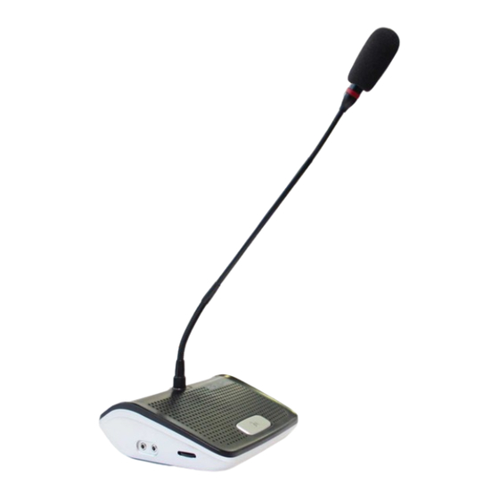
Chapter 3 Conference Unit TL-3300 3.1 Overview The TL-3300 conference unit provides basic functions: including speaking, listening, attendance registration and automatic camera tracking. The conference units include chairman unit and delegate unit. The only difference between them is that the chairman unit has an extra priority (PRIO) key. -
Page 17: Installation And Connection Of Tl-3300
TL-3300 Digital Conference Systems 3.3 Installation and Connection of TL-3300 3.3.1 Connection with T-shaped Cable To connect the T-shaped cable (8P-T3) to the conference unit, insert the female connector of the 0.5m cable from the conference unit into the male connector of one end from the T-shaped cable, then insert the male connector of another end from this T-shaped cable into the female connector of the previous T-shaped cable. -
Page 18: Operation Of Tl-3300
Refer to the following figure: 3. 4 Operation of TL-3300 After all wires are connected, power on all devices. When the central control unit makes a ”tick” sound, the conference unit can be operated. -
Page 19: Chapter 4 Cables And Configuration
TL-3300 Digital Conference Systems Chapter 4 Cables and Configuration 4.1 Cables 4.1.1 Connection Cable (8P-T3) for Conference Unit Technical indicators Color: black Type: 8PS Connector: male connector x 2; female connector x 1 Length: 1.5 + 1.2m Note: Generally, each conference unit is configured with one such cable. -
Page 20: Repeater
4.2 Repeater Technical indicators Color black Type: RS-485 repeater Interface: 8-pin female connector x 2; 13-pin female connector x 2 Dimension: 110×64×38mm Material: aluminum Note: If system wiring length exceeds 50m, add a repeater (generally, this device is connected after an extension cable or in the middle of the bus). -
Page 21: Chapter 5 System Connection And Basic Setting
8P-T3 cable. Generally, this cable is hidden in drawer of a table or in flower on the table. If actual distance exceeds this cable, use the extension cable 8PS-03\05\10\15\20\40 developed by GONSIN or STP cable (8×φ0.2 double shielded, welding is needed) for extension. During welding, make sure correct interconnection. -
Page 22: Connection Of Central Control Unit And Conference Units
DIN8M-B connector Color of Blue Shielded 1 Shielded 2 Orange White/ White/ Brown White/ White/blue Green wire orange green brown DIN8F-A connector Color of Blue Shielded 1 Shielded 2 Orange White/ White/ Brown White/ White/blue Green wire orange green brown DIN8M-C connector 5.1.3 Connection of Central Control Unit and Conference Units... -
Page 23: Wiring Of Extension Cable
TL-3300 Digital Conference Systems 5.2 Wiring of Extension Cable 8PS-03/05/10/15/20/40 and 13PS-03/05/10/15/20 will be used for wiring. Roundtable conference: for an extension cable, its male connector is located at the control room for connecting to the central control unit and its female connector is located at the table for connecting to the first conference unit. -
Page 24: Chapter 6 Technical Indicators
Chapter 6 Technical Indicators 6.1 Technical Parameters of Central Control Unit (TL-Z3) Product TL-Z3 Central control unit for basic discussion function Parameter Model Item Frequency response 30HZ~20KHZ Distortion rate Harmonic distortion (THD) < 0.3% Signal to noise ratio -95dB Sensitivity High (77dB), medium (80dB), low (82dB) Power source AC110/220V±10% 50/60Hz... -
Page 25: Technical Parameters Of Conference Unit (Tl-3300)
TL-3300 Digital Conference Systems 6.2 Technical Parameters of Conference Unit (TL-3300) Product TL-VX3300/ TL-VD3300 Basic discussion unit Mounting type Tabletop Frequency response 30HZ~20KHZ -46dB±4dB Sensitivity (THD)<0.3% Harmonic distortion S/N ratio -95db Power source Working temperature 0~45°C Storage temperature -20~50°C Dimension L×W×H 160×140×55mm... -
Page 26: Chapter 7 Faqs
Chapter 7 FAQs 1. Q: After the central control unit is powered on, it makes a ”tick” sound. Only the chairman unit is enabled and all delegate units are not enabled. Why? A: System communication is abnormal, so the central control unit cannot detect delegate units. ①Check the communication wires (orange or orange/white) for open circuit or short circuit. -
Page 27: Appendix
¤ GONSIN makes every effort to ensure accuracy and conciseness of the contents in this document. For any inaccuracy due to print error, please contact us, and we will correct it in a timely manner. ¤... - Page 28 GONSIN Conference Equipment Co., Ltd.
Need help?
Do you have a question about the TL-3300 and is the answer not in the manual?
Questions and answers