Advertisement
Quick Links
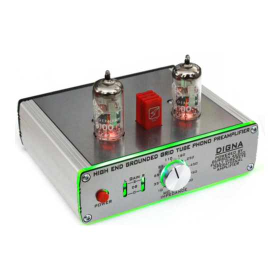
Assembly Manual DIGNA
Foreword
Dear audio friend,
Thank you for purchasing this state-of-the-art phono preamp DIY kit. You have purchased a
product that captivates as a DIY version a component quality and choice of materials that is
unique in the market and many industrially manufactured high-end products should attract
warm theirselves .
However, this also means that you should not "cobble together" this kit in record time. Take a
quiet evening and about four hours time to build.
Also, you should already have the necessary equipment and knowledge to be able to build
such a high-quality DIY kit without complications. The resulting success will definitely reward
you for your effort and stamina.
The instructions assume electronic fundamentals, i.e. you already know that ICs, LEDs and
electrolytic capacitors are poled components and may not be soldered in reverse polarity.
Furthermore, the usage of a temperature-controlled soldering station with max. 1 mm wide
tip and correspondingly fine electronic solder as well as appropriate tools (multimeter, TX10
screwdriver, side cutter, tweezers, magnifying glass, etc.) are advised.
Please follow the steps and tips and hints in this manual. These are all tried out and
tested and allow you a trouble-free setup.
Important Safety Instructions
During installation, commissioning and measurements and repair special care is required!
Assembling of the circuit is at your own risk. The functionality can not be guaranteed, nor the
suitability for certain purposes. The user himself has to check this and is responsible for this
suitability. No liability can be accepted for damages arising during or as a result of the assembly
or operation, in particular for damages resulting from a lack of electronic skills.
The phono preamplifier may only be operated in a touch-proof housing in dry indoor enviroment.
Operation without or with defective tubes is not permitted!
The person who has completed a kit or has made an assembly ready by extension or encolure
installation, is according to VDE 0869 a manufacturer and therefore provided to supply all
documents when selling the device and also give his name and address. Devices which are
assembled from kits themselves are to be considered as an industrial product in terms of
safety.
And now, my friend - fire your soldering station now ...
Power Supply Board
We'll start by assembling and checking the power supply board first. The SMD components
are already assembled and soldered on the solder side, so that our work is limited to the
assembly of the few through hole components and the two M3 x 13 spacers, which are fixed
from the solder side with two Torx screws M3 x 4.
Tip: Please solder only one pin of the 10-pin header BL1 first and align it exactly vertically.
Also, press the S3 switch all the way down to the PCB before soldering it. Also keep care
about the correct polarity of the 1000µF electrolytic capacitor.
Seite 1
Advertisement

Related Manuals for Burson DIGNA


Summary of Contents for Burson DIGNA
- Page 1 Assembly Manual DIGNA Foreword Dear audio friend, Thank you for purchasing this state-of-the-art phono preamp DIY kit. You have purchased a product that captivates as a DIY version a component quality and choice of materials that is unique in the market and many industrially manufactured high-end products should attract warm theirselves .
- Page 2 Assembly Manual DIGNA Now check how the power supply Connect the module to the supplied 12V power supply and switch on. Now use a multimeter to measure the voltage at the test points against TP GND: A tolerance of 5% at the 12 V measuring points and 3% at the 64 V measuring point is in order.
- Page 3 Assembly Manual DIGNA 10 ohms 330 ohms 10 k 16.2 k 31.6 k 49.9 k 82.5 k 267 k To better find the individual resistances on the PCB their values are marked in different colors. Seite 3...
- Page 4 12 o'clock (ie "upwards" in the direction of the component side). Now fix the knob with its grub screw. Finally, solder the two transformers UT1 / UT2 and the BURSON operational amplifier. Note the orientation of the BURSON amplifier (the kangaroo emblem must face to the front).
- Page 5 PCB after peeling off the protective foil. You will notice that it gets a little bit "tight" when placed in at the area around the BURSON operational amplifier. This is intended and serves as an additional safeguard against accidental falling out. However, with the help of a fingernail (around the BURSON), the cover can easily be pressed flush.
- Page 6 DIGNA Phono Tube Preamplifier Rev.10-17 Power Supply Board SMT components preassembled and soldered Pos. Type Value/Package Remarks SS14L / SS16L Schottky Diode Sub SMA D1…D17 2u2 100V ceramic 1210 C24,C25,C41….C58,C61 15V 500mW Zener Diode MiniMelf BCX 51 / 52 / 53...
Need help?
Do you have a question about the DIGNA and is the answer not in the manual?
Questions and answers