Table of Contents
Advertisement
Quick Links
Advertisement
Table of Contents

Related Manuals for EURA VDP-22A3 PLUTON G


Summary of Contents for EURA VDP-22A3 PLUTON G
- Page 1 VIDEO DOORPHONE VDP-22A3 PLUTON G User Manual...
-
Page 2: Table Of Contents
INITIAL REMARKS Before assembling, wiring and setting up of device the user should carefully read gi- ven manual. In case of any troubles with understanding the content the user should contact the producer. Unassisted assembling and start of the device can be done only with the use of proper tools. -
Page 3: Devices Construction
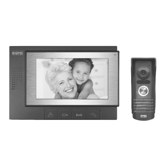
1. DEVICES CONSTRUCTION The VDP-22A3 Video doorphone set consists of: - VDA-02A3 indoor unit (monitor) for home installation, - VDA-10A3 outdoor unit (video doorphone camera) for outdoor installation, - DC power supply, - accessories (rain cover). This monitor is equipped with a 7 inch color LCD display. In addition to the standard communication functions with the visitor, the camera preview and controlling the en- trance to the property, the monitor can controls the second entrance. -
Page 4: Devices Installation
OUTDOOR VIDEO DOORPHONE CONSTRUCTION 1. Camera 2. Speaker 3. LED light 4. Call button 5. Microphone 6. Mounting holes 7. Connection terminal 8. Rain shade Fig.5 Fig.6 2. INSTALLATION CAUTION! Recommended length and cross-sections of cables connecting both modules: The connection to the electromagnetic bolt should be 0 - 50m 4x0.5mm carried out by 2 x 1 mm2 cable, similar to the connection to... -
Page 5: Outdoor Video Doorphone Installation
Mount the monitor on the 4 bracket mounting hooks Plug in the power supply ~230V/50Hz. 2.2. OUTDOOR VIDEO DOORPHONE INSTALLATION The outdoor unit is factory adapted for surface mounting. CAUTION! The proper location of the outdoor video doorphone unit determines the comfort of working with it. -
Page 6: Wiring Diagram
To properly install outdoor station: Unscrew the lower fixing screw and separate the outdoor unit from the rain cover. With 3 holes in the bottom of the protective roof, uncheck on the wall the places for moun- ting pins (fig 9). In the marked places, drill 3x Ø5mm mounting holes and place there 3 fixing pins (fig. -
Page 7: Usinig Vdp-22A3 Video Doorphone
CAUTION! Control of the entrance gate is realized by relay whose contacts N.O. (Normally open) are output to terminals 7 and 8 of the monitor. CAUTION! All power and communication wire that have a direct contact with the wire used to connect indoor and outdoor unit could cause malfunctioning. -
Page 8: Connecting Vdp-22A3 With Additional Uniphone
button inside the property, to manually run the gate drive. It is possible to connect to the terminals 7 and 8 of the standard electromagnetic lock, to open the second gate to the property (fig. 13). Then, a separate power supply with parameters adjusted to the parameters of this bolt should be used for powering the bolt. - Page 9 CAUTION! 1. The electric-lock can be opened by uniphone and monitor, provided by the proper polarity with electric-lock power supply. 2. When called from the outdoor video doorphone, the signal is triggered simul- taneously in the monitor and uniphone. When you press the Talk button on the monitor, the uniphone continues to emit a chime signal - until you lift the handset or automatically switch off the chime (after three beeps).
- Page 10 BEFORE YOU CALL - TROUBLE SHOOTING No Picture / Signal Solution No Picture / Signal - Make sure all the connection are secure and properly connected. - Make sure your monitor is plugged into a po- wer source. - Make sure there is nothing obstructing the view of the camera.
-
Page 11: Technical Data
7. TECHNICAL DATA System EURA Connect Monitor unit VDA-02A3 Video doorphone unit VDA-11A3 Power supply VZA-63A3 Working Voltage 12 V DC Video signal 1Vp-p 75 Ohm CCIR Connecting wire Number of apartments Number of supported inputs Intercom Expansion Monitor VDA-02A3... - Page 12 Water proof rating IP44 Video doorphone working temperature -18ºC ~ +50ºC Video doorphone size (H x W x D) 144 x 64 x 52 mm Video doorphone weight 178g...
- Page 13 EU Conformity Declaration of this device is available on http://www.eura-tech.eu website EURA-TECH Sp. z o.o. 84-200 WEJHEROWO, ul. Przemysłowa 35A, POLAND www.eura-tech.eu All rights reserved. Pictures, graphs and texts are the property of “Eura-Tech” Sp. z o.o. Copying, distributing and publication without permission of author is forbidden.
Need help?
Do you have a question about the VDP-22A3 PLUTON G and is the answer not in the manual?
Questions and answers