
Related Manuals for CTS FRG-3105 Series


Summary of Contents for CTS FRG-3105 Series
- Page 1 FRG-3105 Series Residential Gateway Network Management User’s Manual Version 0.90...
- Page 2 Trademarks Contents are subject to revision without prior notice. All other trademarks remain the property of their respective owners. Copyright Statement Copyright 2017, All Rights Reserved. This publication may not be reproduced as a whole or in part, in any way whatsoever unless prior consent has been obtained from Company.
- Page 3 Revision History Version Firmware Date Description 0.90 0.99.06 20170713 First Release...
-
Page 4: Table Of Contents
Table of Contents 1. INTRODUCTION ..........................6 1.1 Management Options ................................7 1.2 Interface Descriptions ................................7 1.3 Connecting the Residential Gateway ............................8 2. Command Line Interface (CLI) ......................8 2.1 Remote Console Management - Telnet ............................ 8 2.2 Navigating CLI ..................................9 2.2.1 General Commands ................................ - Page 5 3.5.2 VLAN Settings ................................. 75 3.5.3 VLAN State ..................................76 3.6 LAN Setup ....................................77 3.6.1 LAN IP & DHCP Server ..............................78 3.6.2 Interface Group ................................79 3.6.3 DHCP Reservation ................................80 3.6.4 LAN IPv6 & DHCPv6 Server ............................. 82 3.6.5 DHCPv6 Server Reservation ............................
-
Page 6: Introduction
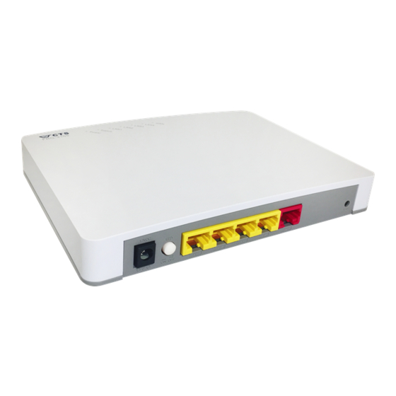
1. INTRODUCTION Thank you for purchasing the WLAN Residential Gateway which is designed to aim at FTTX applications. This WLAN Residential Gateway provides four TP ports for LAN applications, one fiber optic or TP port for WAN. The WLAN Residential Gateway is mainly dedicated to the FTTX broadband service providers who look for a way of delivering multiple IP services to the home users. -
Page 7: Management Options
1.1 Management Options Management options available in this Residential Gateway are listed below: CLI Management Web Management SNMP Management (See 4. SNMP NETWORK MANAGEMENT for detailed descriptions.) 1.2 Interface Descriptions Before you start to configure your device, it is very important that the proper cables with the correct pin arrangement are used when connecting the Residential Gateway to other devices such as switch, hub, workstation, etc. -
Page 8: Connecting The Residential Gateway
user then can configure and check the Residential Gateway even when the network is down. 1.3 Connecting the Residential Gateway Before starting to configure the Residential Gateway, you have to connect your devices correctly. When you connect your device correctly, the corresponding LEDs will light up. ... -
Page 9: Navigating Cli
Step 3. Log into the Gateway CLI Limitations: When using Telnet, keep the following in mind: Only two active Telnet sessions can access the Gateway at the same time. 2.2 Navigating CLI When you successfully access the Gateway, you will be asked for a login username. Enter your authorized username and password, and then you will be directed to User mode. -
Page 10: Command Format
table summarizes the most frequently used quick keys in CLI. Keys Purpose Enter an unfinished command and press “Tab” key to complete the command. Press “?” key in each mode to get available commands. Enter an unfinished command or keyword and press “?” key to complete the command and get command syntax help. -
Page 11: Login Username & Password
[-s size] [-r repeat] [-t timeout] These three parameters are used in ping command and are optional, which means that you can ignore these three parameters if they are unnecessary when executing ping command. [A.B.C.D ] Brackets represent that this is a required field. -
Page 12: User Mode
Enable Mode Password Enable mode is password-protected. When you try to enter Enable mode, a password prompt will appear to request the user to provide the legitimate passwords. Enable mode password is the same as the one entered after login password prompt. By default, no password is required. Therefore, press Enter key in password prompt. -
Page 13: Traceroute Command
Gateway> ping 8.8.8.8 –s 128 –t 10 2.3.2 Traceroute Command Traceroute is used to trach the path between the local host and the remote host. Enter the traceroute command in User mode. In this command, you can add an optional max hops value for the number of hops that packets are sent and received. - Page 14 A:B:C:D:E:F:G:H] [file name] Enter the configuration file name that you [file name] want to restore. [user_name] [user_name] Enter the username for FTP server login. [password] [password] Enter the password for FTP server login. Gateway# copy-cfg [A.B.C.D | Enter the IP/IPv6 address of your TFTP from tftp [A.B.C.D | A:B:C:D:E:F:G:H] server.
-
Page 15: Firmware Command
A:B:C:D:E:F:G:H] [file name] Enter the configuration file name that you want to [file name] [running backup. | default | startup ] [running | default Specify backup config to be running, default or [user_name] | startup ] startup [password] [user_name] Enter the username for FTP server login. [password] Enter the password for FTP server login. -
Page 16: Ping Command
Gateway# firmware upgrade tftp 192.168.1.198 HS_0600_file.bin 2.4.3 Ping Command Ping is used to test the connectivity of end devices and also can be used to self test the network interface card. Enter the ping command in User mode. In this command, you can add an optional packet size value and an optional value for the number of times that packets are sent and received. -
Page 17: Write Command
2.4.6 Write Command To save running configurations to startup configurations, enter the write command. All unsaved configurations will be lost when you restart the Gateway. Command / Example Gateway# write Save Config Succeeded! 2.4.7 Configure Command The only place where you can enter Global Configuration mode is in Privileged mode. You can type in “configure”... -
Page 18: Configuration Mode
DHCP Vendor ID: Enter the Vendor ID used for DHCP relay agent function. Firmware Version: Display the firmware version used in this device. Current Boot Image: The image that is currently using. Configured Boot Image: The image you want to use after reboot. Image-1 Version: Display the firmware version 1 (image-1) used in this device. -
Page 19: Entering Interface Numbers
Set up required configurations for Network Time Protocol. Set up the priority of packets within the Managed Switch. security Security global configuration commands. show Show a list of commands or show the current setting of each listed command. snmp-server SNMP server configuration commands. system-info Set up acceptable frame size and address learning, etc. -
Page 20: Advanced Command
Company Name: Display a company name for this Gateway. Use “system-info company-name [company-name]” command to edit this field. System Object ID: Display the predefined System OID. System Contact: Display contact information for this Gateway. Use “system-info system-contact [sys-contact]” command to edit this field. System Name: Display a descriptive system name for this Gateway. -
Page 21: Applications Command
MAC address of its own. WAN MAC Address “Generation”, each interface has a unique MAC address of their own. No Command Gateway(config)# no advanced Return WAN MAC address to default. wan-mac 2.5.5 Applications Command 1. Set up DMZ function. Command Parameter Description Gateway(config)# applications... - Page 22 its service will be inaccessible from the Internet. To open the service to hosts on the Internet, the network administrator may adopt Port Forwarding feature. Port Forwarding allows an IP address on the private network to be accessed from an IP address on the public network.
-
Page 23: Interface Command
2.5.6 Interface Command Use “interface” command to set up configurations of several discontinuous ports or a range of ports. 1. Entering interface numbers. Command Parameter Description Gateway(config)# interface lan [port_list] Enter several lan port numbers separated [port_list] by commas or a range of port numbers. For example: 1,3 or 2-4 Gateway(config)# interface wan [port_list]... - Page 24 Gateway(config-net-PORT- Configure port duplex to half. PORT)# no duplex Note1 : Only copper ports can be configured as half duplex. Note2 : Auto-negotiation needs to be disabled before configuring duplex mode. 5. Enable flow control operation. Command Parameter Description Gateway(config-net-PORT- Enable flow control on port(s).
-
Page 25: Ip Command
Note1 : Speed can only be configured when auto-negotiation is disabled. Note2: Fiber ports can not be configured as 10Mbps. No command Gateway(config-net-PORT- Undo port speed setting. PORT)# no speed 9. Set up VLAN parameters per port. Command Parameter Description Gateway(config-net-PORT- [1-4094] Configure port PVID. - Page 26 domain name so the host can be found on the internet with this domain name. With DDNS, the network administrator can access the Residential Gateway with a permanent domain name even if it is often assigned different IP addresses by DHCP. And users on the Internet can access the server (such as the web service) on the private network by the domain name of the Residential Gateway.
- Page 27 Gateway(config)# ip dhcp [domain-name] Specify the domain name of the Residential server domain-name Gateway up to 30 characters. [domain-name] Gateway(config)# ip dhcp [1-14400] Specify the lease time in minute. This is a time server ip-lease-time [1- period in which the DHCP clients can keep their 14400] IP addresses since the last time in which they receive the DHCP acknowledgement packet...
- Page 28 Interface Grouping supports multiple clients to PVC and bridging groups, each group will perform as an independent network, if any other information not in compliance with the criteria will be forwarded to Data Interface. To support this feature, you must create mapping groups with appropriate LAN Criteria and WAN interfaces.
- Page 29 multicast list for that group. And, when the Gateway hears an IGMP Leave, it removes the host's port from the table entry. IGMP snooping can very effectively reduce multicast traffic from streaming and other bandwidth intensive IP applications. A Gateway using IGMP snooping will only forward multicast traffic to the hosts interested in that traffic.
- Page 30 Gateway(config-static-route- [1-15] Specify metric value. Metric is the cost of a no.)# metric [1-15] route to a destination network. No command Gateway(config)# no ip igmp Disable IGMP/MLD Snooping function. snooping Gateway(config)# no ip igmp Disable immediate leave function. snooping immediate-leave Show command Gateway(config)#show ip igmp Show current IGMP/MLD snooping status...
- Page 31 ip mtu [68-1500] packets which the Residential Gateway will transmit. MTU stands for “Maximum Transmission Unit.” Gateway(config-data-1)# vlan-id [1-4094] Specify a VLAN ID for the WAN interface. [1-4094] And the WAN interface will add this VLAN ID to the egress untagged packets. ( This parameter is only available when the WAN information is Data, Management) Gateway(config)# ip wan-...
- Page 32 management interface is not created on the Residential Gateway. Gateway(config-iptv-1)# active Enable the WAN interface entry specified. Gateway(config-iptv-1)# [dhcp | Specify the way of IP distribution, either connection-type [dhcp | static-ip] static-ip] DHCP or static IP mode. Gateway(config-iptv-1)# dhcp [68-1500] Specify the DHCP MTU for optimal mtu [68-1500] performance.
-
Page 33: Ipv6 Command
Gateway(config- Return connection type to default setting data/management/iptv/voip -1)# no connection-type Gateway(config- Return DHCP connection to default setting data/management/iptv/voip -1)# no dhcp Return DNS server to default setting. Gateway(config-data-1)# no dns Gateway(config- Disable Ping access function. data/management/iptv/voip -1)# no ping-access Gateway(config- Return Static IP connection to default data/management/iptv/voip -1)#... - Page 34 Gateway(config)# no ip ddns authentication Set IPv6 DDNS Authentication type to default. Gateway(config)# no ip ddns host-name Clear the host name. Gateway(config)# no ip ddns password Clear the password. Gateway(config)# no ip ddns token Clear IPv6 DDNS token Gateway(config)# no ip ddns username Clear IPv6 DDNS user name Show command Gateway(config)#show ipv6 ddns...
- Page 35 Gateway(config)# ipv6 dhcpv6 [0-255] Enter the server preference level for the server preference [0-255] DHCP server in the Server Preference field. If multiple DHCP servers exist in a network, the server with the highest preference level is allowed to assign the addresses. Gateway(config)# ipv6 dhcpv6 Enable Rapid Commit which allows the server rapid-commit-option...
- Page 36 4. Set up IPv6 Router Advertisement Daemon (RADVD) IPv6 Router Advertisement Daemon (RADVD) broadcasts auto-configuration parameters and responds to Router Solicitations from clients that are trying to configure. A Router Advertisement message is issued periodically by a router or in response to a Router Solicitation message from a host.
- Page 37 radvd advertise Gateway(config)# no ipv6 Set advertise interval back to default. radvd interval Gateway(config)# no ipv6 Disable RA managed flag. radvd ra-managed-flag Gateway(config)# no ipv6 Set RA MTU option back to default. radvd ra-mtu Gateway(config)# no ipv6 Disable RA other flag radvd ra-other-flag Gateway(config)# no ipv6 Disable RDNSS function.
- Page 38 Gateway(config)# ipv6 wan- Specify the number of static route. interface data [1] Gateway(config-data-1)# active Enable global interface. Gateway(config-data-1)# [dhcpv6 | link- Specify connection type. connection-type [dhcpv6 | link- local-only | local-only | pppoe-ipv6 | static- pppoe-ipv6 | ipv6 | 6in4-tunnel | 6rd-tunnel | static-ipv6 | 6to4-tunnel |] 6in4-tunnel |...
- Page 39 Gateway(config-data-1)# 6rd- [auto | manual] Configure 6rd tunnel mode. tunnel action [auto | manual] Gateway(config-data-1)# 6rd- [A.B.C.D] Configure 6rd tunnel border relay IP tunnel manual boader-relay address. [A.B.C.D] Gateway(config-data-1)# 6rd- [0-32] Specify IP mask length. tunnel manual mask-length [0- Gateway(config-data-1)# 6rd- [a:b:c:d:e:f:g:h] Specify 6rd tunnel prefix IPv6 address.
-
Page 40: Management Command
1)# 6rd-tunnel action [auto | manual] Gateway(config- management - [A.B.C.D] Configure 6rd tunnel border relay IP 1)# 6rd-tunnel manual boader- address. relay [A.B.C.D] Gateway(config- management - [0-32] Specify IP mask length. 1)# 6rd-tunnel manual mask- length [0-32] Gateway(config- management - [a:b:c:d:e:f:g:h] Specify 6rd tunnel prefix IPv6 address. - Page 41 Gateway(config)# Permit the computers to manage the management access- Residential Gateway from its WAN ports. control wan Gateway(config)# Gain the SNMP management access on management access- WAN port. control wan snmp Gateway(config)# Gain the Telnet management access on management access- WAN port.
- Page 42 interval will start counting at the beginning of communication session. Gateway(config)# Specify the time in second after which a management cwmp-agent piece of information will be sent again. parameter-change notify The default value is 60. interval [1-86400] No command Gateway(config)# no Deny the computers to manage the management access- Residential Gateway from its LAN ports.
-
Page 43: Ntp Command
password Gateway(config)# no Clear the username for Auto Configuration management cwmp-agent Server. management-server username Gateway(config)# no Clear HTTP address of the Auto management cwmp-agent Configuration Server. management-server url Gateway(config)# no Disable or disable Periodic Information management cwmp-agent function. parameter-change notify Gateway(config)# no Return the time interval to default value. - Page 44 Gateway(config)# ntp [1-5] Specify a NTP server for the Residential server option [1-5] Gateway to update its internal clock from an NTP server. If there is no particular NTP server which you prefer, you can select the given one of the default NTP servers.
-
Page 45: Qos
Gateway(config)# ntp server ip 192.180.0.12 Set the time server IP address to 192.180.0.12. Gateway(config)# ntp syn-interval 4 Set the synchronization interval to 4 hours. Gateway(config)# ntp time-zone 3 Set the time zone to GMT-8:00 Vancouver. 2.5.11 QoS 1. Set up Qos QoS command Parameter Description... -
Page 46: Security Command
1048576] kbps kbps Gateway(config-if-PORT-PORT)# [port | queue] Configure egress rate mode qos rate-limit egress [port | queue] Gateway(config-if-PORT-PORT)# [0-7] Specify the default priority bit to the qos user-priority [0-7] selected interfaces. No command Gateway(config-if-PORT-PORT)# no qos default- Undo default queue on the port class Gateway(config-if-PORT-PORT)# no qos rate-limit Delete QoS ingress rate limit... - Page 47 applications [1-11] Where: 1:FTP 2:SSH 3:Telnet 4:SMTP 5:DNS 6:HTTP 7:POP 8:NNTP 9:IMAP 10:SNMP 11:HTTPS Gateway(config- [A.B.C.D] [1-254] Specify the source IP address range of application-No.)# source-ip- the packets which will be denied by this range [A.B.C.D] [1-254] rule. Gateway(config)# security [1-10] Specify the entry number of lan packet packet-filter lan [1-10]...
- Page 48 Gateway(config-wan-No.)# Enable this WAN rule. active Gateway(config-wan-No.)# [A.B.C.D] Specify the destination IP address of the destination ip [A.B.C.D] packets which will be denied by this rule. Gateway(config-wan-No.)# [1-65535] Specify the destination port number of the destination port-number [1- packet which will be denied by this rule. 65535] Gateway(config-wan-No.)# [tcp | udp]...
- Page 49 Gateway(config-mac-No.)# Return port number to default value 1 no destination port-number Gateway(config-mac-No.)# Return MAC address to default value no mac-address 00:00:00:00:00 Gateway(config-mac-No.)# Return protocol to default value TCP. no protocol Gateway(config-wan-No.)# Disable the configured WAN rule. no active Gateway(config-wan-No.)# Return IP address to default value 0.0.0.0 no destination ip Gateway(config-wan-No.)# Return port number to default value 1...
- Page 50 Gateway(config-url-No.)# Disable the rule. no active Gateway(config-url-No.)# Clear the URL address. no url Show Command Gateway(config)# show url- Shows the current configuration of URL filter filter. 4. Set up VPN Passthrough This feature enables the VPN traffic to be transmitted from the private network of the Residential Gateway to the public network.
- Page 51 between devices. An UPnP device can dynamically join a network, obtain an IP address, convey its capabilities and learn about other devices on the network. In turn, a device can leave a network smoothly and automatically. No Command Gateway(config)# no Disable UPnP function.
- Page 52 999] Gateway(config)# security Enable to prevent a SYN attack on a ddos per-source-ip syn specified IP address. Gateway(config)# security [1-999] Specify the packets per second. ddos per-source-ip syn [1- 999] Gateway(config)# security Enable to prevent a UDP attack on the ddos per-source-ip udp LAN port IP address.
- Page 53 requests. Gateway(config)# security [1-999] Specify the packets per second. ddos whole-system-flood syn [1-999] Gateway(config)# security Enable to prevent a flood of large ddos whole-system-flood numbers of raw UDP packets targeted at the Residential Gateway. Gateway(config)# security [1-999] Specify the packets per second. ddos whole-system-flood udp [1-999] No Command...
-
Page 54: Snmp Command
chargen Gateway(config)# no Disable FIN flood attack prevention security ddos whole- system-flood fin Gateway(config)# no Disable ICMP flood attack prevention security ddos whole- system-flood icmp Gateway(config)# no Disable SYN flood attack prevention security ddos whole- system-flood syn Gateway(config)# no Disable UDP flood attack prevention security ddos whole- system-flood udp Show Command... - Page 55 account, system information and load factory settings. ro: Read Only access privilege. No command Gateway(config)# no snmp- [community] Delete the specified community. server community [community] Gateway(config-community- Disable this SNMP community account. In this example “mycomm” community is NAME)# no active disabled.
- Page 56 Gateway(config)# no snmp- [1-2] Delete the specified trap destination server trap-destination [1-2] account. Gateway(config-trap- Disable this SNMP trap destination ACCOUNT)# no active account. Gateway(config-trap- Delete the configured community name. ACCOUNT)# no community Gateway(config-trap- Delete the configured trap destination ACCOUNT)# no description description.
-
Page 57: Syslog Command
power-down: A trap will be sent when the power is off. warm-start: A trap will be sent when the device restarts. No command Gateway(config)# no [all | auth-fail Specify a trap type that will not be sent snmp-server trap-type [all | | case-fan | when a certain situation occurs. -
Page 58: System-Info Command
Gateway(config)# no syslog Disable System log function. Gateway(config)# no syslog level Return Syslog level to default level. Gateway(config)# no syslog server Delete the primary system log server IP address. Show command Gateway(config)# show syslog Show current system log settings. Gateway(config)# show log Show event logs currently stored in the Gateway. -
Page 59: User Command
Gateway(config)# no system-info system- Delete the entered system name name information. Gateway(config)# no system-info host-name Set the hostname to the factory default. Show command Gateway(config)# show system-info Show or verify Gateway information including system contact, system location, system name, model name, firmware version and fiber type. -
Page 60: Vlan Command
Gateway(config-user- [password] Enter the password, up to 20 alphanumeric NAME)# password characters, for this user account. [password] No command Gateway(config)#no user [username] Delete the specified account. name [username] Gateway(config-user- Deactivate the selected user account. NAME)# no active Gateway(config-user- Remove the configured description. NAME)# no description Gateway(config-user- Remove the configured password value. -
Page 61: Web Management
3. WEB MANAGEMENT This chapter describes how to manage the Residential Gateway through a Web browser. The IP address concepts and gaining access to the Residential Gateway will be introduced first, and then followed by web-based management instructions. 3.1 The Concept of IP address IP addresses have the format n.n.n.n, for example 168.168.8.100. - Page 62 Run a Web browser and specify the Residential Gateway’s IP address to reach it. (The default IP of Residential Gateway is “192.168.0.1” before any changes.) Login to the Residential Gateway to reach the Main Menu. Once you gain the access, a Login window appears like the following: Enter the authorized user name and password then click “Login”.
-
Page 63: Introduction To Sub-Menus
3.3 Introduction to Sub-Menus If you successfully login to the web management, the first page you will see is as follows: Main Menu Bar Configuration Area Main Menu Bar At the left of the screen page is the Main Menu bar. It contains the following main tabs: -... - Page 64 UPnP - Enable or disable UPnP function. - Set up port forwarding function. Port Forwarding - DMZ stands for “Demilitarized Zone”. Set up DMZ function. - This page enables the network administrator to change the settings of the Time Residential Gateway’s internal clock. Dignostics -...
-
Page 65: System Information
3.4 System Information Select Syatem Information from the Main Menu bar. Then you can see the sub-items – System, Fiber Information, SFP Status – on the sub menu bar. 3.4.1 System Select System from the System Information sub menu bar. Then, System screen page appears as follows:... - Page 66 This page displays basic information of the Residential Gateway and information about the SFP transceiver plugged in the WAN port. And for more details, please refer to the description of the individual section below. System This is a view-only section which displays basic system information of the Residential Gateway.
- Page 67 System Location — Display a brief location description for this Residential Gateway. DHCP Vendor ID — Enter the Vendor ID used for DHCP relay agent function. Model Name — Display the product’s model name. Host Name — This is the host name of the Residential Gateway. Current Boot Image —...
- Page 68 Speed — This is the maximal link speed which the fiber transceiver supports. Distance — This is the maximal transmission distance which the fiber transceiver supports. Vendor Name — This is the name of the manufacturer. Vendor PN — This is the model name of the fiber transceiver. Vendor SN —...
-
Page 69: Wan Setup
3.5 WAN Setup This page enables the network administrator to configure the general settings of the Residential Gateway. Select WAN Setup to access this page. And it will appear as follows: And for details on the settings of this page, please refer to the description of the individual section below. - Page 70 This section shows the basic information of the WAN interfaces of the Residential Gateway. Below is a description of each column in the list. Status - It is Enabled if the WAN interface is activated. And it is Disabled if the WAN interface is deactivated.
- Page 71 Type - This is the Internet connection type of this WAN interface. VLAN - This is the VLAN ID which this WAN interface will add to the egress untagged packets. P-Bit -This is the 802.1p priority value which this WAN interface will add to the egress untagged packet together with its VLAN ID.
- Page 72 Data - The data interface is the default WAN Interface of the Residential Gateway. It is open to remote management from the IP specified in the Device Access web page when the management interface is not created on the Residential Gateway. Management -...
- Page 73 IPTV - The IPTV interface(Data Interface) is for IPTV data transmission. It is open to remote management from the IP specified in the Device Access web page when the management interface is not created on the Residential Gateway. VoIP - The VoIP interface(Data Interface) is for VoIP data transmission. It is open to remote management from the IP specified in the Device Access web page when the management interface is not created on the Residential Gateway.
- Page 74 Static MTU - Specify the maximal size of Ethernet packets which the Residential Gateway will transmit. MTU stands for “Maximum Transmission Unit.” DNS1 - Specify the IP address of the primary DNS server of the WAN interface. ( This parameter is only available for the data interface. ) DNS2 -...
-
Page 75: Vlan Settings
3.5.2 VLAN Settings Select one of the following two system operation modes for the Residential Gateway in the pull- down menu: Inside NAT VLAN - This is the PVID of the LAN port on the private network. Interface - Specify NAT or Bridge mode for each port. This section shows which LAN ports are on the private network (inside NAT) and which LAN ports are on the public network (outside NAT). -
Page 76: Vlan State
Access - Set the selected port to access mode (untagged). Trunk - Set the selected port to trunk mode (tagged). Trunk-Native - Enable native VLAN for untagged traffic on the selected port. Mode Port Behavior Receive untagged packets only. Drop tagged packets. Access Send untagged packets only. -
Page 77: Lan Setup
according to their original VLAN tags. If the original VLAN tags of the tagged packets are the same as the WAN port’s PVID, the packets will be untagged by the Residential Gateway. Otherwise, they will keep their original VLAN tag when they leave the Residential Gateway. -
Page 78: Lan Ip & Dhcp Server
3.6.1 LAN IP & DHCP Server This section allows you to assign a private IP address to the Residential Gateway and to configure the DHCP server function of the Residential Gateway. LAN IP is an IP address which the Residential Gateway has on the private network. DHCP Server enables the Residential Gateway to assign IP addresses to the hosts on the private network. -
Page 79: Interface Group
Note that the private network and the public network of the Residential Gateway should not be overlapped. Otherwise, the Residential Gateway cannot forward the packets to the correct destination. DHCP Server - Enable or disable the DHCP server function of the Residential Gateway. Domain Name -... -
Page 80: Dhcp Reservation
Interface Group- Globally enable or disable Interface Group function. Group Name - Specify a name for the group. Enable - Click to enable or disable the entry. WAN Interface - Show the type of WAN interface used. Criteria - Show the criteria used and specify the vendor class identifier. Action -... - Page 81 IP-MAC Binding Mode - Select the desired mode to use, either Allocation or Access Restriction. Description - This is a brief description for this entry. IP - This is an IP address which you want to reserve for a specific DHCP client. MAC -...
-
Page 82: Lan Ipv6 & Dhcpv6 Server
DHCP Client List displays information such as the hostname, the IP address, the type of the IP address, the MAC address and the expire time of the leased IP address. Click Refresh to update the DHCP client list. Click Apply to submit your settings after you finish configuring this table. 3.6.4 LAN IPv6 &... - Page 83 DHCPv6 Mode - Specify the mode of DHCPv6 server, either Stateless or Stateful mode. Domain Name - Enter a domain name for the DHCP server. Server Reference - Enter the server preference level for the DHCP server in the Server Preference field.
-
Page 84: Dhcpv6 Server Reservation
3.6.5 DHCPv6 Server Reservation Index - The entry of each IPv6 address. IPv6 Address - Specify the IPv6 address. DUID - The DHCP Unique Identifier (DUID). Description - Add the remark to description box. Action - Click Check Icon to add a new entry after you configure it in the textboxes of the table. - Page 85 Router Advertisement - Enable or disable Router Advertisement. This option allows the router to reply to the Router Solicitation messages. Advertisement Mode - Unsolicited Multicast indicates the router periodically broadcasts Router Advertisement messages and responds to Router Solicitations from clients. Unicast Only indicates the router only responds to Router Solicitations from clients.
-
Page 86: Fire Wall
RA MTU Oprion - Enter the largest packet (in bytes) that can be sent without fragmentation in the MTU field. The MTU is determined by the ISP but is normally 1500 bytes. Router Lifetime - Enter (in seconds) how long a route created by the Router Advertisement message should remain valid in the Router Lifetime field. -
Page 87: Port Forwarding
Click this drop-down box then click OK button to enable UPnP feature. UPNP provides compatibility with networking equipment, software and peripherals. 3.9 Port Forwarding A host on the private network of the Residential Gateway is invisible from the Internet for it is protected by the firewall. - Page 88 Port Forwarding Table This section allows you to create or modify a port forwarding rule which will be executed by the Residential Gateway. Below is a description of configuration parameters in this section. Enable — Select the checkbox if you want to enable this rule. Protocol —...
-
Page 89: Dmz
3.10 DMZ DMZ stands for “Demilitarized Zone”. It is an IP address on the private network of the Residential Gateway. But it is exposed to the Internet for special-purpose services. So a host on the private network can be assigned the IP address of the DMZ to provide services to the hosts on the Internet. - Page 90 Select DMZ from menu bar. Then, DMZ screen page appears as follows: DMZ Settings This section allows you to create or edit the DMZ of a selected interface in the Interface List. Below is a description of configuration parameters in this section.
-
Page 91: Time
Current DMZ Status — Enable or disable the DMZ of the selected WAN interface. Source IP — Select Any IP Address to expose the DMZ to any IP address on the Internet. Or you can select the other radio button and specify an IP address range in the text boxes so the DMZ will be exposed to the IP address in the specified IP address range only. -
Page 92: Time Zone Setting
3.11.1 Time Zone Setting This section enables you to make the date and time settings of the Residential Gateway. Below is a description of the configuration parameters of this section. Date Time Setting — Specify the date and time in the text boxes to set the internal clock of the Residential Gateway manually. -
Page 93: Dignostics
Time Zone — Select your time zone from the pull-down menu. Daylight Saving Time — To enable or disable the daylight saving time function. Daylight saving time is the practice of advancing clocks during summer months by one hour so that evening daylight lasts an hour longer, while sacrificing normal sunrise times. Daylight Saving Time Date Start —... -
Page 94: Ping
3.12.1 Ping This section allows you to use ICMP to check the connectivity between the Residential Gateway and a host on the Internet. Below is a description of the configuration parameters of this section. Ping IP Address — Specify an IP address as the destination of the ICMP Ping packets. Count —... -
Page 95: Backup/Restore
traceroute command in User mode. In this command, you can add an optional max hops value for the number of hops that packets are sent and received. IP/URL Address — Specify target IP address or URL. 3.13 Backup/Restore Select Backup/Restore from menu bar. Then, Backup/Restore screen page will appear as follows: 3.13.3 Backup/Restore This section enables you to create a backup file for the current configuration of the Residential... - Page 96 Server — Click to choose the Server type HTTP or FTP. User Name — Enter the specific username to access the File Server. Password — Enter the specific password to access the File Server. Config Type — There are three types of Config Type: Running-config, Default-config and Start-up-config.
- Page 97 Restore using FTP— You may restore configuration using FTP server as long as following the procedure below. Action — Click to choose Restore Config. Server — Click to choose FTP. Server IP Address— Enter the specific IP address of the File Server. User Name —...
-
Page 98: Factory Default
Assumed that we have a setting of existing User Previlidge in DUT and a configure file ready to be loaded. Existing DUT User New Configure file of User Write Protection Previlidge Accounts: Previlidge Accounts:: Level “home” 1. Superuser 1. Superuser 2. -
Page 99: Save & Logout
system “REMOTELY” because conventional Factory Reset will bring network settings back to default and lose all network connections. Click Reset to reset the Gateway to the default settings. Select Save and Logout from Administration sub menu bar. Then, Save and Logout screen page will appear as follows: 3.15 Save &... -
Page 100: Advaned
Reboot Device Click Reboot Device to restart the Residential Gateway. Next bootup Image Click drop-down box to select Image and click Set Next bootup Image to set the desired next bootup Image. 3.15 Advaned 3.15.1 Setup 3.15.1.1 DDNS DDNS stands for “Dynamic Domain Name Service”. It allows a host to bind with a permanent domain name so the host can be found on the internet with this domain name. - Page 101 Username - Specify the username provided by the DDNS server. Password - Enter the password provided by the DDNS server. Host Name - Enter the DDNS URL assigned by the DDNS server.. Click Apply to submit your settings after you finish configuring this page. DDNS State This is a view-only section.
- Page 102 Username - Specify the username provided by the DDNS server. Password - Enter the password provided by the DDNS server. Token - Enter the token issed by the vendor. Host Name - Enter the DDNS URL assigned by the DDNS server.. Click Apply to submit your settings after you finish configuring this page.
- Page 103 WAN MAC Address is set “Generation”, each interface has a unique MAC address of their own. 3.15.1.3 Routing Setup This page allows the network administrator to decide how the Residential Gateway will process the received packets. Select Routing Setup from the Setup sub menu bar. Then, Routing Setup screen page appears as follows: 3.15.1.3.1 Static Routing This section allows you to edit or modify an entry in the Static Route Table of the Residential...
- Page 104 Static Route Table Enable - Click to enable the configured static route. Destination IP Address - Specify the destination IP address of the static route. Netmask - Specify the subnet mask of the destination network of the static route. Gateway - Specify the IP address of a gateway through which this static route will send the packets to the destination network.
- Page 105 3.15.1.3.3 IPv6 Static Routing Enable - Click to enable the configured static route. Destination IPv6 Address/Prefix Length - Specify the destination IPv6 address of the static route. Gateway - Specify the IPv6 address of a gateway through which this static route will send the packets to the destination network.
-
Page 106: Security
3.15.1.3.4 IPv6 Routing Table This table displays all the static routes created on the Residential Gateway. Click Refresh to renew the current status of routing table. 3.15.2 Security 3.15.2.1 Packet Filter This function enables the Residential Gateway to filter out the unwanted packets according to the IP address, the source MAC address or the application protocol. - Page 107 Packet Filter Rule Enable or disable the packet filter function. When it is enabled, the Residential Gateway will drop packets which meet predetermined conditions of the rules in the following sections. WAN Filter This section allows you to edit the WAN filter rules. The WAN filter rule will block packets which are received by the Residential Gateway from the public network and match the...
- Page 108 pre-determined condition of the rule. Below is an explanation for each column of the rule table. Enable — Enable or disable this WAN filter rule. Source IP Range — Specify an IP address range for the WAN filter rule to block packets whose source IP addresses are in this range.
- Page 109 Source IP Range — Specify an IP address range for the LAN filter to block packets whose source IP addresses are in this range. Destination IP — Specify an IP address range for the LAN filter to block packets whose destination IP addresses are in this range.
- Page 110 Destination IP — Specify the destination IP address of the packets which will be denied by this rule. Dest. Port — Specify the destination port number of the packet which will be denied by this rule. Protocol — Select TCP or UDP in the pull-down menu as the communication protocol inside the packet which will be denied by this rule.
- Page 111 Click Apply Packet Filter to submit your settings after you finish configuring this page. 3.15.2.2 URL Filter URL Filter enables the network administrator to deny computers to access the specific websites on the Internet from the private network of the Residential Gateway. Select URL Filter from the Security sub menu bar.
- Page 112 Action — Click Add URL Filter to add a new rule to the table after you configure it in the text boxes. Then, click Check Icon to submit the new settings. If you need to remove any entry from this table, click Cross Icon. Click Apply URL Filter to submit your settings after you finish configuring this page.
- Page 113 L2TP Pass Through — Enable or disable the L2TP pass through on the Residential Gateway. L2TP stands for “Layer 2 Tunneling Protocol”. It is used to enable Point-to- Point sessions via the Internet on the Layer 2 level. Click OK to submit your settings after you finish configuring this page. 3.15.2.4 DDoS The Residential Gateway supports DDoS Prevention.
- Page 114 This section allows you to configure the DDoS prevention feature to prevent the Residential Gateway from malicious attacks. Below is a description of configuration parameters in this section. Enable DoS Prevention — Tick the checkbox to activate DDoS prevention manually. And select the kinds of DDoS attacks to enable the Residential Gateway to detect them.
- Page 115 TCP/UDP Port Scan — Tick the checkbox to prevent a series of systematic queries to the Residential Gateway for open ports through which to route traffic. ICMP Smurf — Tick the checkbox to prevent the hacker to forge the IP address of the Residential Gateway and send repeated ping requests to it flooding the network.
-
Page 116: Qos
packets/second — Specify the number of packets per second that you want to scan for malicious activity. Sensitivity — Select High or Low from the pull-down menu for the sensitivity of the TCP/UDP port scan prevention. Click Select All to select all of kinds of DDoS attacks in the checkboxes. Or click Clear all to unselect all of the checkboxes. - Page 117 3.15.3.1 QoS Priority QoS stands for the “Quality of Service”. It allows the network administrator to give traffic of a service a higher priority for bandwidth to ensure its quality. Some services on the Internet, like the multimedia service, require larger bandwidth than the other services do. So the network administrator needs QoS to guarantee that their traffics will not be assigned too few bandwidth when there are many other traffics in the same link.
- Page 118 For details on the settings, please refer to the description of the individual section below. QoS Priority Configuration: The Residential Gateway supports QoS of the egress traffic. QoS of the Residential Gateway provides four queues for packet transmission – Queue 0, Queue 1, Queue 2 and Queue 3.
- Page 119 DSCP — Select this mode to bind the DSCP values of the packets with the designated queues. And packets will be assigned to different queues according to their DSCP values. The Residential Gateway will follow the priority orders or the ratio of the transmission rates of the queues which store the packets to transmit packets.
- Page 120 If you select Port for the Priority Mode and weighted for the Queue Mode, you need to specify the ratio of the transmission rates of the queues to decide how the ports of the Residential Gateway will be mapped to the queues. Queue Weight(Q0:Q1:Q2:Q3) —...
- Page 121 If you select 802.1p for the Priority Mode and weighted for the Queue Mode, you need to specify the ratio of the transmission rates of the queues and decide how the 802.1p value should be mapped to the queues. Queue Weight(Q0:Q1:Q2:Q3) — Specify the ratio of the transmission rate for queues in the text boxes.
- Page 122 DSCP Priority Mode > Weighted Queue Mode If you select DSCP for the Priority Mode and weighted for the Queue Mode, you need to specify the ratio of the transmission rates of the queues and determine how the DSCP value should be mapped to the queues. Queue Weight(Q0:Q1:Q2:Q3) —...
- Page 123 For details on the settings, please refer to the description of the individual section below. Rate Limit Configuration This section contains a table which displays the current rate limit settings of the Residential Gateway. It allows you to set the maximum rate limit of the ingress and egress traffic on each port.
-
Page 124: Iptv
Egress Rate — Select per port to give an egress rate limit to the port. Select per queue to give an egress rate limit to each queue for this port. Or select disable to deactivate this feature. Egress Bandwidth Q0 — If you select Per Port for the Egress Rate, specify the rate limit for the egress traffic of the port in the text box. - Page 125 3.15.4.1 IGMP Control The Residential Gateway supports the IGMP snooping and the IGMP proxy. IGMP stands for “Internet Group Management Protocol”. It is widely used by the multimedia services which rely on the multicast protocol to conduct multimedia streams to the hosts (such as IPTVs). When a host makes a request for the multimedia stream of a channel, it will send a request packet to join the multicast group of this channel to the multicast router.
-
Page 126: Management
IGMP Snooping/Proxy Enable or disable the IGMP snooping and IGMP proxy function on the Residential Gateway. When the IGMP host is on the private network, the IGMP proxy must be activated for the Residential Gateway to learn the request of the host. And when the IGMP host is on the public network, the IGMP snooping must be enabled for the Residential Gateway to learn this request of the host. - Page 127 3.15.5.1 DHCP Auto Provision This section allows you to enable or disable the DHCP auto-provisioning function. DHCP Auto Provision — Click to enable or disable DHCP Auto Provision Click OK to submit your settings after you finish configuring this page.
- Page 128 3.15.5.2 CWMP Agent TR-069 (Technical Report 069) is a technical specification that defines an application layer protocol for remote management of end-user devices. As a bidirectional SOAP/HTTP-based protocol, it provides the communication between customer-premises equipment (CPE) and Auto Configuration Servers (ACS). It includes both a safe auto configuration and the control of other CPE management functions within an integrated framework.
- Page 129 Note: If a communication session has been incomplete for long time, the time interval will start counting at the beginning of communication session. Periodic Change Notify Interval — Specify the time in second after which a piece of information will be sent again. The default value is 60. Connect Request User Name —...
- Page 130 This section allows you to make proper settings on the Residential Gateway so you can manage the Residential Gateway by SNMP. Below is a description of the configuration parameters of this section. Account State — Shows the SNMP service is Enable or Disable. SNMP Level —...
- Page 131 Account State — Enable or disable the SNMP service. Community — Specify the authorized SNMP community name Description —Enter a unique description for this community name. This is mainly for reference only. SNMP Level — Specify user’s authentication level. Administrator: Full access right including maintaining user account & system information, load factory settings …etc.
- Page 132 State — Enable or disable the function of sending trap to the specified destination. Destination — Enter the specific IP address of the network management system that will receive the trap. Community — Enter the community name of the network management system. Action —...
-
Page 133: Administration
Cold Start Trap — Enable or disable the Gateway to send a trap when the Gateway is turned on. Warm Start Trap — Enable or disable the Gateway to send a trap when the Gateway restarts. Authentication Failure Trap — Enable or disable the Gateway to send authentication failure trap after any unauthorized users attempt to login. - Page 134 3.15.6.2 Management Access This section allows you to configure the management methods for the Residential Gateway. Below is a description of the configuration parameters of this section.
- Page 135 HTTP Management Port — This is Internet socket port numbers used by protocols of the transport layer of the Internet Protocol Suite for the establishment of host-to-host connectivity. The default value is 80. Allow Remote IP address — Select Any IP Address for the Residential Gateway to be managed from its WAN port by any remote IP address.
- Page 136 3.15.6.4 Port Configuration This section displays the port state of the Residential Gateway. You can click drop-down arrow in each column of the table to configure the settings of the selected port in the next section. Below is a description of the configuration parameters of this section. Port Number —...
- Page 137 Port Type — This is a view-only field. It indicates that the selected port is in the auto- negotiation mode so this port will negotiate with the other device to link up in the maximum link speed. And the port of the device on the other side should support auto- negotiation as well.
- Page 138 Syslog — Tick the checkbox to enable this feature. Or untick the checkbox to deactivate Syslog Server IP Address — Specify the IP address of the Syslog server in the text box. Syslog Level — Select one of the syslog levels from the pull down menu. The Residential Gateway will record log events at the chosen level and above.
- Page 139 Account State — Shows the entry is enabled or disabled. Privilege Level — Shows which authority the account is qualified for. Three privilege levels as follows. Superuser — Full access right, including maintaining user account, system information, loading factory settings, etc.. Editor —...
- Page 140 Account State — Enable or disable this user account. User Name — Specify the authorized user login name, up to 20 alphanumeric characters. Password — Enter the desired user password, up to 20 alphanumeric characters. Retype Password — Enter the password again for double-checking. Description —...
- Page 141 3.15.6.9 TFTP Upgrade Server — Select the TFTP protocol. Upgrade Image Option — Select the Image you want to boot up. Server IP Address — Enter the specific IP address of the File Server. File Location — Enter the specific path and filename within the File Server. Click OK to start the download process and receive files from the server.
- Page 142 3.15.6.10 FTP Upgrade Server —Select the FTP protocol. Upgrade Image Option — Select the Image you want to boot up. Server IP Address — Enter the specific IP address of the File Server. User Name — Enter the specific username to access the File Server. Password —...
-
Page 143: Status
Upgrade Image Option — Select the Image you want to boot up. Select File —Click browse, select the desired file. Click OK to start the download process and receive files 3.15.7 Status Select Status in the Menu bar. And the sub-items – WAN, LAN, WiFi, Routing Table, Port Status and Event Log–... - Page 144 This is a view-only section which displays information about the WAN port’s status and the WAN interfaces of the Residential Gateway. Below is a description of each item in this section. MAC Address — This is the MAC address of the Residential Gateway on the public network.
- Page 145 IPv6 Type — This is the Internet access type of this WAN interface. VLAN — This is the VLAN ID of this WAN interface. P-Bit — This is the P-bit value of this WAN interface. Global IPv6/Prefix Length — This is the global IPv6 address which this interface has. Link-local IPv6/Prefix Lenth —...
- Page 146 IP Address — This is the private IP address of the Residential Gateway. Subnet Mask — This is the subnet mask which the Residential Gateway has for its private IP address. DHCP Server — It is Enabled when the DHCP server function of the Residential Gateway is activated.
- Page 147 IPv6 LAN Status: This is a view-only section which displays information about the the Residential Gateway on the private network. Below is a description of each item in this section. MAC Address — This is the MAC address which the Residential Gateway has on the private network Global IPv6 Address —...
- Page 148 DHCP Client List This is a view-only section. It displays the list of the DHCP clients which are assigned IPv6 addresses by the Residential Gateway. Index — The number of each client assigned. Type — Shows the type of each host. IPv6 Address —...
- Page 149 Index — The number of each route assigned. Destination IP Address —The destination IP address of the route. Netmask — The subnet mask of the destination network of the route. Gateway — The IP address of a gateway through which this route will send the packets to the destination network.
- Page 150 Index — The number of each route assigned. Destination IPv6 Address/Prefix Length —The destination IPv6 address of the route. Gateway — The IPv6 address of a gateway through which this route will send the packets to the destination network. Metric — Metric is the cost of a route to a destination network. Interface —...
-
Page 151: Wizard
Port Number — This is the port number. Config. Port State — This field shows if the port is enabled or disabled. Media Type — It is the media type of this port, either Copper or Fiber. Link Status — It is the current link status of the port, either Link Up or Link Down.. Port Speed —... -
Page 153: Snmp Network Management
4. SNMP NETWORK MANAGEMENT The Simple Network Management Protocol (SNMP) is an application-layer protocol that facilitates the exchange of management information between network devices. It is part of the TCP/IP protocol suite. SNMP enables network administrators to manage network performance, find and solve network problems, and plan for network growth. -
Page 154: Appendix A: Set Up Dhcp Auto-Provisioning
APPENDIX A: Set Up DHCP Auto-Provisioning Networking devices, such as switches or gateways, with DHCP Auto-provisioning function allow you to automatically upgrade firmware and configuration at startup process. Before setting up DHCP Server for auto-upgrade of firmware and configuration, please make sure the Residential Gateway that you purchased supports DHCP Auto-provisioning. - Page 155 Step 2. Prepare “dhcpd.conf” file You can find this file in Linux ISC DHCP server. /usr/local/etc/dhcpd.conf Step 3. Copy the marked text to “dhcpd.conf” A sample of dhcp text is provided in Appendix B. Please copy the marked area to “dhcpd.conf” file. Copy the text to dhcpd.conf file Sample dhcp text...
- Page 156 Step 4. Modify “dhcpd.conf” file Modify the marked area with your own settings. This value is configurable and can be defined by users. Specify the protocol used (Protocol 1: FTP; Protocol 0: TFTP). Specify the FTP or TFTP IP address. Login FTP server anonymously.
- Page 157 Step 5. Generate a Configuration File Before preparing the configuration image in TFTP/FTP Server, please make sure the device generating the configuration image is set to “Get IP address from DHCP” assignment. This is because that DHCP Auto-provisioning is running under DHCP mode, so if the configuration image is uploaded by the network type other than DHCP mode, the downloaded configuration image has no chance to be equal to DHCP when provisioning, and it results in MD5 never match and causes the device to reboot endlessly.
- Page 158 B. Auto-Provisioning Process This Residential Gateway is setting-free (through auto-upgrade and configuration) and its upgrade procedures are as follows: The ISC DHCP server will recognize the device whenever it sends an IP address request to it. And ISC DHCP server will tell the device how to get a new firmware or configuration. The device will compare the firmware and configuration MD5 code form of DHCP option every time when it communicates with DHCP server.
-
Page 159: Appendix B: Dhcp Text Sample
192.168.2.1 192.168.2.99; option subnet-mask 255.255.255.0; option broadcast-address 192.168.2.255; option routers 192.168.2.2; option domain-name-servers 168.95.1.1, 168.95.192.1, 192.168.2.2; host CTS-FAE { hardware ethernet 00:14:85:06:5A:06; fixed-address 192.168.2.99; #Please copy the text below to your dhcpd.conf file# option space SAMPLE; # protocol 0:tftp, 1:ftp option SAMPLE.protocol code 1 = unsigned integer 8;... - Page 160 This page is intentionally left blank. evision History Manual Version Modification Firmware Version Date Revise description of Phone NO., Length of NO., Delete Length, and Prefix No. in 2011/11 Section 2.9.7. 0.99 Add multi-user & tone customization (Revise 1.01.37 2011/05 Administrator Account &...
Need help?
Do you have a question about the FRG-3105 Series and is the answer not in the manual?
Questions and answers