Table of Contents
Advertisement
FWRIII-3105 SERIES
4 ports 10/100/1000Mbps RJ-45; built-in IEEE802.11n WiFi and 1 port 1000Mbps SFP slot
4 ports 10/100/1000Mbps RJ-45; built-in IEEE802.11n WiFi and 1 port 100/1000Mbps SFP
4 ports 10/100/1000Mbps RJ-45; built-in IEEE802.11n WiFi and 1 port 100/1000Mbps fiber
4 ports 10/100/1000Mbps RJ-45; built-in IEEE802.11n WiFi and 1 uplink port combo
(10/100/1000Mbps RJ-45 and 100/1000Mbps SFP slot) Residential Gateway
4 ports 10/100/1000Mbps RJ-45; built-in IEEE802.11n WiFi and 1 port 100/1000Mbps fiber
4 ports 10/100/1000Mbps RJ-45; built-in IEEE802.11n WiFi and 1 uplink port combo
(10/100/1000Mbps RJ-45 and 100/1000Mbps SFP slot) Residential Gateway
4 ports 10/100/1000Mbps RJ-45; built-in IEEE802.11n WiFi and 1 port 10/100/1000Mbps
uplink Residential Gateway
slot uplink Residential Gateway
optics uplink Residential Gateway
optics uplink Residential Gateway
RJ-45 uplink Residential Gateway
User's Guide
Version 0.99.00
Advertisement
Table of Contents

Related Manuals for CTS FWRIII-3105 SERIES


Summary of Contents for CTS FWRIII-3105 SERIES
- Page 1 FWRIII-3105 SERIES 4 ports 10/100/1000Mbps RJ-45; built-in IEEE802.11n WiFi and 1 port 1000Mbps SFP slot uplink Residential Gateway 4 ports 10/100/1000Mbps RJ-45; built-in IEEE802.11n WiFi and 1 port 100/1000Mbps SFP slot uplink Residential Gateway 4 ports 10/100/1000Mbps RJ-45; built-in IEEE802.11n WiFi and 1 port 100/1000Mbps fiber optics uplink Residential Gateway 4 ports 10/100/1000Mbps RJ-45;...
- Page 2 Trademarks CTS is a registered trademark of Connection Technology Systems Inc.. Contents subject to revision without prior notice. All other trademarks remain the property of their respective owners. Copyright Statement Copyright 2013 Connection Technology Systems Inc.. This publication may not be reproduced as a whole or in part, in any way whatsoever unless prior consent has been obtained from Connection Technology Systems Inc..
-
Page 3: Table Of Contents
Table of Contents 1. INTRODUCTION ................... 4 1.1 The WLAN Residential Gateway .............. 4 1.2 Appearance ....................6 2. INSTALLATION ................... 10 2.1 Installation Requirements ............... 10 2.2 Checking the Package Contents ............10 2.3 Installing the WLAN Residential Gateway ..........11 2.4 Powering ON .................. -
Page 4: Introduction
1. INTRODUCTION Thank you for choosing this WLAN Residential Gateway. The WLAN Residential Gateway can provide the best performance and price ratio when multiple copper ports need to be deployed in networking environment. 1.1 The Managed Residential Gateway With 4 or 5 10/100/1000Mbps RJ-45 ports on the front panel and 4 wireless LAN for IEEE802.11N standards, this compact WLAN Residential Gateway provides high performance store-and-forward switching capability plus other advanced features such as QoS, VLAN, etc.. - Page 5 MAC Address Table: 1K Store-and-Forward Switching Mechanism Support up to 9k Jumbo Frames Support IEEE802.1Q Tag VLAN VLANs: Support up to 128 VLAN Groups Support IGMP Proxy Support IGMP Snooping V1 and V2 ...
-
Page 6: Appearance
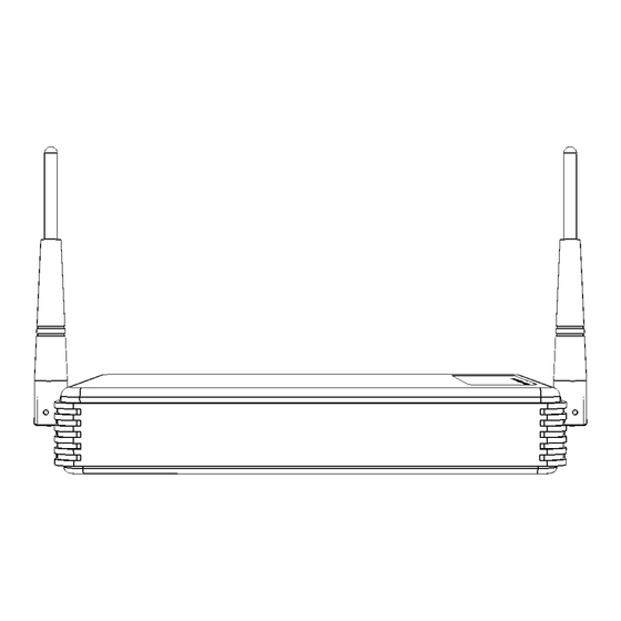
1.2 Appearance Front Panel ➊ ➋ 4 ports 10/1000Mbps RJ-45; built-in IEEE802.11n WiFi and 1 uplink port Figure 1. Front Panel for combo (10/100/1000Mbps RJ-45 and 100/1000Mbps SFP slot) Residential Gateway 4 ports 10/100/1000Mbps RJ-45; built-in IEEE802.11n WiFi and 1 uplink port combo Figure 2. -
Page 7: Rear Panel
Rear Panel Figure 3. Rear Panel for 4 ports 10/100/1000Mbps RJ-45; built-in IEEE802.11n WiFi and 1 port 10/100/1000Mbps RJ-45 uplink Residential Gateway ➌ Figure 4. Rear Panel for 4 ports 10/100/1000Mbps RJ-45; built-in IEEE802.11n WiFi and 1 port 100/1000Mbps fiber optics uplink Residential Gateway ➌... - Page 8 Left and Right Panel Figure 5. Left Panel ➎ ➏ Figure 6. Right Panel Power Jack Connector ➎ WPS Button ➏ Reset Button: Insert a pin or paper clip to press the Reset Button for 5 seconds to restart the system ...
-
Page 9: Top Panel
Top Panel ➐ Figure 7. Top Panel ➐ LED: For detail definitions, please refer to chapter 3.1 LED Definitions Cable Specifications The following table contains various cable specifications for the WLAN Residential Gateway. Please make sure that you use the proper cable when connecting the WLAN Residential Gateway. -
Page 10: Installation
2. INSTALLATION To properly install the WLAN Residential Gateway, please follow the procedures listed below. Procedures covered in this chapter are described below in separate sections. Installation Requirements Unpacking the WLAN Residential Gateway Installing the WLAN Residential Gateway ... -
Page 11: Installing The Wlan Residential Gateway
2.3 Installing the WLAN Residential Gateway CAUTION To prevent any damage or failure of the WLAN Residential Gateway, please DO NOT block the ventilation FAN holes. Use the following guidelines when choosing a place to install the Residential Gateway: Firm and steady flat surface. ... -
Page 12: Connecting The Gateway To Network
2.5 Connecting the Gateway to Network Connect to Network This WLAN Residential Gateway has 4 or 5 10/100/1000Mbps RJ-45 ports on the front panel. These ports can be inserted by 10/100/1000Base-T cables, connecting to the end devices. The connection of the fiber port on the rear panel must be matched, i.e. -
Page 13: Operation
3. OPERATION The WLAN Residential Gateway is Plug & Play compliant. Real-time operational status can be monitored through a set of LED indicators located on the top panel. A built-in management module provides users with flexible interfaces to configure, control and monitor the complete system remotely. 3.1 LED Definitions Color Operation... -
Page 14: Maintenance
4. MAINTENANCE It is easy to use and maintain this WLAN Residential Gateway. The procedures are suggested when you want to identify faults, perform hardware replacement and firmware upgrading. 4.1 Fault Identification Identifying faults can greatly reduce the time required to find the problem and solution. -
Page 15: Hardware Replacement Procedures
4.2 Hardware Replacement Procedures WARNING! The WLAN Residential Gateway contains no user-serviceable parts. DO NOT, UNDER ANY CIRCUMSTANCES, open and attempt to repair it. Failure to observe this warning could result in personal injury or death from electrical shock. Failure to observe the above warning will immediately void any Warranty. 4.3 Firmware Upgrade This WLAN Residential Gateway may perform firmware upgrading when required.
Need help?
Do you have a question about the FWRIII-3105 SERIES and is the answer not in the manual?
Questions and answers