Table of Contents
Advertisement
Advertisement
Table of Contents

Related Manuals for GLIDEAWAY MICA


Summary of Contents for GLIDEAWAY MICA
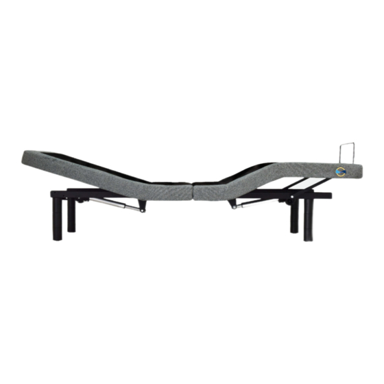
- Page 1 MICA OWNERS MANUAL Comfort Base ® Gold Series...
-
Page 2: Table Of Contents
Contents Safety Information ................2 What Is Included ................5 Assembly - Base ................6 Location of Controls - Remote ..........11 Operation - Main ................12 Operation - Linking the Remote ..........13 Troubleshooting ................14 Available Accessories ..............15 Online Resouces................16 User Info Please take a moment and write down the serial number in the space provided below, in case you need to refer to it in the future. -
Page 3: Safety Information
SAFETY INFORMATION ATTENTION! IMPORTANT SAFETY INSTRUCTIONS. SAVE THIS MANUAL! PLEASE READ THESE INSTRUCTIONS THOROUGHLY BEFORE USING THIS PRODUCT. PROPER OPERATION OF YOUR ADJUSTABLE BED IS NECESSARY TO ENSURE THE LONG LIFE AND DURABILITY YOU EXPECT FROM A HIGH-QUALITY PRODUCT. THE MANUFACTURER HAS TESTED AND INSPECTED THIS PRODUCT PRIOR TO SHIPMENT. - Page 4 SAFETY INFORMATION WARRANTY WARNING! This bed is speciically designed to require no maintenance by you, the user. Any opening or tampering with the control box, motors or hand controls (with the exception of the battery compartment, if equipped) will void the warranty. Do not attempt to alter component wiring or adjust or modify the structure of the product in any way or the warranty will be void.
- Page 5 SAFETY INFORMATION SMALL CHILDREN AND PETS WARNING Immediately dispose of all packing materials as they can pose a smothering risk to small children and pets. Injury could also occur if children or pets are permitted to play on or under the bed. Do not allow children to operate this bed without adult supervision. LUBRICATION AND CLEANING This product is designed to be maintenance-free.
-
Page 6: What Is Included
WHAT IS INCLUDED Before discarding any packing materials, check the adjustable base shipping carton and verify the following items are included: (2) Base Pieces (8) Hex Bolts with (1) Allen Key (2) Connecting Rods (1) Foot Mattress Retainer (4) Multi-Height Low Proile Legs (Overall Bed height 8”, 11.5”... -
Page 7: Assembly - Base
ASSEMBLY - BASE It is HIGHLY recommended to use two people for the installation of this product. To assemble, please perform the following steps: Carefully lift both Base Pieces from the shipping carton, keeping the unit’s top- side down. Remove the plastic wrapping from the bottom to access the bases. - Page 8 ASSEMBLY - BASE FIGURE Please Refer to diagram when assembling the adjustable bed. Motor-to-DC Cable Motor-to-Control DC Power Cord Lead Wire Power Supply Foot and Head Motor To AC Connector Cables Outlet NOTE: Make sure wire connected to Power Supply is routed UNDER the main metal frame and lifting mechanism.
- Page 9 ASSEMBLY - BASE Insert the AC cord into the power supply. IMPORTANT: DO NOT PLUG THE BASE INTO THE AC OUTLET YET. Insert the legs into the threaded holes at Insert the legs into the threaded holes at each corner of the base by inserting the leg and rotating clockwise until tight.
- Page 10 ASSEMBLY - BASE Remove the Mattress Retainer Bar from the bottom of the base. Finish removing the plastic packaging from the base to orient into inal position. Carefully rotate the base on its side, then lift and place on legs. IMPORTANT: DO NOT LEAN THE BED AGAINST THE INSTALLED LEGS TO TURN OVER.
- Page 11 ASSEMBLY - BASE BASE POWER SUPPLY Lift the battery cover and insert the three AAA size batteries (included) into the remote as shown in the igure. Replace the battery cover. Remote is already linked with the base. Turn the power supply upside down to access the battery cover, then slide the battery cover off.
-
Page 12: Location Of Controls - Remote
LOCATION OF CONTROLS - REMOTE Head and Head Up Foot Up Head and Head Down Foot Down Foot Up Foot Down... -
Page 13: Operation - Main
OPERATION - MAIN Press and hold the Head Up button to raise the Head position. Release button when desired position is reached. Press and hold the Head Down button to lower the head position. Release button when desired position is reached. Press and hold the Foot Up button to raise the foot position. -
Page 14: Operation - Linking The Remote
OPERATION - LINKING THE REMOTE Connecting one Remote to one base Double click the Link button as shown until the LED light on the control box turns on. Release the button and the LED light will turn on. Simultaneously press and hold the Head Up and Foot Up buttons (the left button and middle button located on the top row of the remote) until the remote’s backlight starts lashing. -
Page 15: Troubleshooting
TROUBLESHOOTING In the event the Comfort Base’s base fails to operate, investigate the symptoms and possible solutions provided below: Remote control illuminates • Unplug power cord, wait 30 seconds and plug in to reset electronic and appears to be operable, components. -
Page 16: Available Accessories
AVAILABLE ACCESSORIES Item Part Number High Proile Legs (Overall Bed Height 18.5”) CB12LEG18.5 Headboard Bracket Kit CB05075HBBRKT To order an accessory, please call 1-800-428-5222... -
Page 17: Online Resouces
Online Resources GENERAL INQUIRIES glideaway.com/comfortbase/general SPECIFICATIONS glideaway.com/comfortbase/specificatons TECHNICAL ASSISTANCE Call 1-855-581-3095 or visit glideaway.com/comfortbase/assistance WARRANTY glideaway.com/comfortbase/warranty TROUBLESHOOTING glideaway.com/comfortbase/troubleshooting CARE INSTRUCTIONS glideaway.com/comfortbase/care REGISTRATION glideaway.com/comfortbase/registration TRANSLATIONS For Spanish and French translations visit glideaway.com/comfortbase/userguide... - Page 18 ® Comfort Base Gold Series MICA SKU: CB1810RF 8226 Lackland Road, Saint Louis, MO 63114 | www.glideaway.com | 1-855-581-3095 REV.1.12.18...
Need help?
Do you have a question about the MICA and is the answer not in the manual?
Questions and answers