Advertisement
Quick Links
Installation Manual
Vive Comfort
P.O. Box 3377
Springfield, MO 65804
Toll Free : 888-776-1427
Web: www.vivecomfort.com
Hours of Operation: M-F 9AM - 6PM Eastern
Thermostat Application Guide
Description
Gas or Oil Heat
Electric Furnace
Heat Pump (No Aux. or Emergency Heat)
Heat Pump (With Electric Aux.)
Heat Pump (With Gas Aux.)
Multi-Stage Systems
Heat Only Systems - Floor or Wall Furnace
Cool Only Systems
High and Low Fan Speed
Millivolt
Emergency Heat
Conventional Single Stage Furnace
Geothermal
Table of Contents
Installation Tips
Thermostat Quick Reference
Base Module Tips
Wiring
Wiring Diagrams
Technician Setup
Swing Setting
Reestablishing
Communication
Specifications
U.S. Registered Trademark. Patents pending
Copyright
2018 All Rights Reserved.
Installation Tips
Mount Thermostat
Align the 4 tabs on the subbase with
corresponding slots on the back of the
thermostat, then push gently until the
thermostat snaps in place.
Battery Installation
Battery installation is optional if thermostat is
hardwired (R and C terminal connected to 24V
power).
Important:
High quality alkaline batteries are recommended.
Rechargeable batteries or low quality batteries
do not guarantee a 1-year life span.
Insert 2 AA
Alkaline batteries
(included). High
quality alkaline
batteries are
recommended.
Located on the back of thermostat.
TP-N-631W
Power Type
Battery Power
Hardwire (Common Wire)
Yes
Hardwire (Common Wire) with
Yes
Battery Backup
Yes
Yes
A trained, experienced
No
No
technician must install this
Yes
product.
Yes
Carefully read these
Yes
instructions. You could damage
No
this product or cause a
No
Yes
hazardous condition if you fail
Yes
to follow these instructions.
Page
Una version en español de este
2-3
manual se puede descargar en
4
la pagina web de la compañia.
5-6
7
8-10
11-12
13
14
15
LOW
Wall Locations
The thermostat should be installed approximately 4 to 5 feet above the
floor. Select an area with average temperature and good air circulation.
Installation Tip
Pick an installation location that is easy for
the user to access. The temperature of the
location should be representative of the
building.
Subbase Installation
Horizontal Mount
Vertical Mount
For vertical mount put one screw on the top
and one screw on the bottom.
For horizontal mount put one screw on the
left and one screw on the right.
Rev. 1821
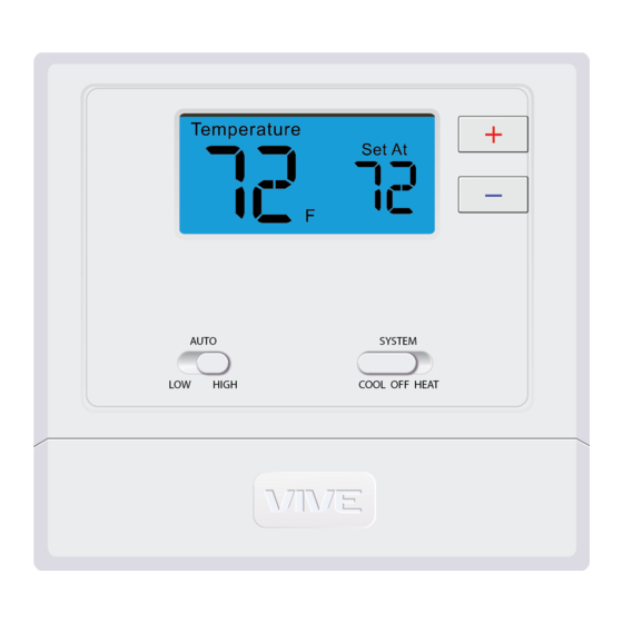
Getting to know your thermostat
HIGH
LOW
HIGH
LCD
Fan Switch
System Switch
Setpoint Buttons
Removing The Private
Label Badge
Use the bevel on lower ridge
Magnet in door
About The Badge
All of our thermostats use the same universal magnetic badge. Visit the
company website to learn more about our free private label program.
Installation Tips
Do not install
thermostat in locations:
• Close to hot or cold air ducts
• That are in direct sunlight
• With an outside wall behind
the thermostat
• In areas that do not require
conditioning
• Where there are dead spots
or drafts
(in corners or behind doors)
• Where there might be
concealed chimneys or
pipes
Installation Tip:
Electrical Hazard
Failure to disconnect the power before
beginning to install this product can
cause electrical shock or equipment
damage.
Mercury Notice
All of our products are mercury free.
However, if the product you are
replacing contains mercury, dispose of
it properly. Your local waste
management authority can give you
instructions on recycling and proper
disposal.
Thermostat Quick Reference
Low Battery
Indicator:
Replace
System operation
Indicates the
batteries when
indicators: On
current room
indicator is
will display when
temperature.
shown.
the COOL or HEAT
is on.
88
88
+1 will appear in the
Displays the
display when the
user selectable
auxiliary heat is active.
setpoint
temperature.
Important
The low battery indicator is displayed when the
AA battery power is low. If the user fails to
replace the battery within 21 days, the screen
will only show the low battery indicator but
maintain all functionality. If the user fails to
replace the batteries after an additional 21 days
(days 22-42 since first "low battery" display) the
setpoints will change to 55˚F (Heating) and 85˚F
(Cooling). If the user adjusts the setpoint away
from either of these, it will hold for 4 hours
then return to either 55˚F or 85˚F. After day 63
the batteries must be replaced immediately to
avoid freezing or overheating because the
thermostat will shut the unit off until the
batteries are changed.
Gently slide a screwdriver into the
bottom edge of the badge. Gently turn
the screwdriver counter clockwise. The
badge is held on by a magnet in the well
of the battery door. The badge should pry
off easily. DO NOT USE FORCE.
Advertisement

Subscribe to Our Youtube Channel
Related Manuals for Vive Comfort TP-N-631W


Summary of Contents for Vive Comfort TP-N-631W
-
Page 1: Subbase Installation
Installation Manual Installation Tips TP-N-631W Wall Locations The thermostat should be installed approximately 4 to 5 feet above the floor. Select an area with average temperature and good air circulation. Vive Comfort Do not install P.O. Box 3377 thermostat in locations: Springfield, MO 65804 •... - Page 2 Base Module Tips Base Module Tips Base Module - PTAC Installation When Working With A Vertical Unit 1. Do not mount Module inside the cabinet of the unit, or in a Range between the thermostat and the base module is up to 100 feet metal enclosure.
- Page 3 Wiring Wiring Diagrams Wiring Wiring Note: Note: If you are replacing a thermostat, make note of the terminal Installation Tip connections on the thermostat that The thermostat and Base Module The base module is is being replaced. In some cases come factory linked (communicating) packaged with labeled Do not overtighten...
-
Page 4: Swing Setting
Specifications Specifications TP-N-631W Thermostat The display range of temperature ... 41˚F to 95˚F (5˚C to 35˚C) The control range of temperature..44˚F to 90˚F (7˚C to 32˚C) Load rating..........1 amp per terminal, 1.5 amp maximum all terminals combined Swing (cycle rate or differential) ..
Need help?
Do you have a question about the TP-N-631W and is the answer not in the manual?
Questions and answers