Table of Contents
Advertisement
Quick Links
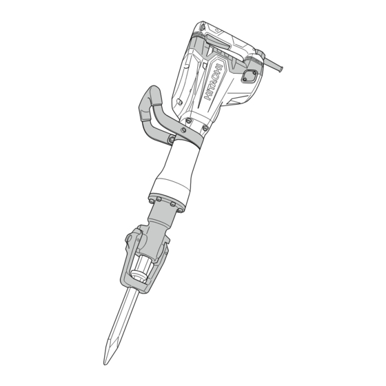
PRODUCT NAME
Hitachi Demolition Hammer
H 65SD3
Model
CONTENTS
REPAIR GUIDE ---------------------------------------------------------------------------------------------------------------- 1
1. Precautions on disassembly and reassembly ----------------------------------------------------------- 1
LIST No.
H 65SD3 : F439
Aug. 2016
Page
Overseas Sales Division
H
Advertisement
Table of Contents

Related Manuals for Hitachi H 65SD3


Summary of Contents for Hitachi H 65SD3
- Page 1 LIST No. H 65SD3 : F439 Aug. 2016 PRODUCT NAME Hitachi Demolition Hammer H 65SD3 Model CONTENTS Page REPAIR GUIDE ---------------------------------------------------------------------------------------------------------------- 1 1. Precautions on disassembly and reassembly ----------------------------------------------------------- 1 Overseas Sales Division...
-
Page 2: Repair Guide
1. Precautions on disassembly and reassembly [Bold] numbers in the description below correspond to the item numbers in the parts list and exploded assembly diagram for the Model H 65SD3. Disassembly NOTE: If it is difficult to loosen and remove the fixing bolts, use an appropriate heating device to heat the bolts to approximately 80°C (176°F). - Page 3 (3) Remove the two Bolts M5 x 16 [59] and five Screws D4 x 25 [90]. Remove handles (A) and (B) of Handle (A). (B) Set [111], four Bolts M5 [105] and Back Cover [78]. Remove the six Bolts M6 x 40 [54], Gear Cover [38], and Counter Gear [63].
- Page 4 4. Removal of the O-rings Because the two O-rings [12] are installed inside the Shank Sleeve [13], it may be difficult to remove. Gently pry the O-rings [12] upward with a small flat-blade screwdriver, while being very careful not to damage the O-ring surface as illustrated in Fig.
- Page 5 4. Mounting the inner cover to the housing ass'y Use a syringe to apply Hitachi Motor Grease No. 29 to the seal ring groove in eight positions as shown in Fig. 5 and then secure the Seal Ring [43] to prevent grease leakage due to misalignment of the Seal Ring [43] at reassembly.
- Page 6 5. Mounting the striker The striker can be mounted in either of the following two ways. • Mount the Connecting Rod Ass’y [28] to the Crank Shaft [48] inside the Housing Ass’y [49]. Mount the Piston [26] and apply grease for hammer. hammer drill (Code No. 980927) to the inside and outside of the Striker [21].
- Page 7 7. Mounting the handle Mount the Handle Stopper [61] to the Gear Cover [38] and secure it with the Back Cover [78]. Be sure to put the two Handle Dampers [57] in Handle Spring (A) [56] and Handle Spring (B) [55] to prevent abnormal noise.
- Page 8 8. Safety precautions on wiring work To prevent breakage and electric shock due to vibration of the Switch [97], the Support [104] elastically holds the Switch [97] in place. Vinyl Tube (A) (I.D. 7 x T0.5 x 50) [98] covers the internal wire, and the Vinyl Tube L55 [74] covers the internal wire of the Stator Ass'y [72].
- Page 9 9. Mounting the retainer (1) Before mounting, apply grease for hammer. hammer drill (Code No. 980927) to the sliding portion between the Retainer [2] and Retainer Damper (A) [4] of the Front Cover [8], and Lever Pin [3]. (2) Mount two Retainer Dampers (A) [4] to the Front Cover [8], and then mount the Retainer [2]. (3) Insert the Lever Pin [3] into the 20-mm dia.
-
Page 10: Lubrication Points And Types Of Lubricant
Lubrication points and types of lubricant Fill specified grease (grease for hammer. hammer drill) to the following parts. • Fill 41 g of specified grease in the Housing Ass'y [49] on the Crank Shaft [48]. • Fill 41 g of specified grease inside the Cylinder Case [19] (on the machined surface). Apply specified grease (grease for hammer. -
Page 11: Screw Tightening Torque
Screw tightening torque +0.98 • Cap Screw [36] ······································································· 4.08 N•m (40 kgf•cm) • Hex. Socket Set Screw M5 x 8 [87] ·············································· 0.49 to 0.98 N•m (5 to 10 kgf•cm) • Nylock Bolt (W/Flange) M5 [105] ················································· 3.92±0.49 N•m (40±5 kgf•cm) •... -
Page 12: Connecting Diagram
Connecting diagram Fig. 14 • Connecting diagram of the product equipped with a noise suppressor Switch Stator Connector Tube Tube Armature Noise suppressor Connector Plug Stator Pillar terminal Fig. 15 • Connecting diagram of the product not equipped with a noise suppressor Switch Stator Tube... - Page 13 LIST NO. F439 DEMOLITION HAMMER 2016 · 8 · 19 Model H 65SD3 (E1)
- Page 14 PARTS H 65SD3 ITEM DESCRIPTION REMARKS CODE NO. USED 994416 ROLL PIN D6 X 55 337040 RETAINER 337041 LEVER PIN 337039 RETAINER DAMPER (A) 306437 NYLOCK HEX. SOCKET HD. BOLT M8 X 30 996369 DAMPER (B) 339702 SECOND HAMMER 339701...
- Page 15 PARTS H 65SD3 ITEM DESCRIPTION REMARKS CODE NO. USED 931008 FEATHER KEY 4 X 4 X 12 960251 HEX. HD. TAPPING SCREW D5 X 65 956764 SPECIAL WASHER 322494 SEAL LOCK HEX. SOCKET HD. BOLT M6 X 40 339697 HANDLE SPRING (B)
- Page 16 PARTS H 65SD3 ITEM DESCRIPTION REMARKS CODE NO. USED 959141 CONNECTOR 50092 (10 PCS.) EXCEPT FOR USA,CAN,MEX 938307 PILLAR TERMINAL EXCEPT FOR BRA,PAN 339675 TAIL COVER 337051 SWITCH 996438 VINYL TUBE (A) (I.D.7 X T0.5 X 50) 337055 INTERNAL WIRE (BLACK)
-
Page 17: Optional Accessories
STANDARD ACCESSORIES H 65SD3 ITEM DESCRIPTION REMARKS CODE NO. USED 339664 CASE (PLASTIC) OPTIONAL ACCESSORIES ITEM DESCRIPTION REMARKS CODE NO. USED 985231 COLD CHISEL 520MM (HEX. SHANK TYPE) 985232 CUTTER W75 X 520MM (HEX. SHANK TYPE) 985233 SCOOP 546L (HEX. SHANK TYPE) 996372 BULL POINT 410MM (HEX.
Need help?
Do you have a question about the H 65SD3 and is the answer not in the manual?
Questions and answers