Advertisement
Quick Links
LUXOMAT
Installation and Operating Instruction for B.E.G.-Occupancy detectors PD4-Master-TRIO-2DALI/DSI-1C-SM/-FC
1. Mounting preparations
Work on the 230 V mains supply
may only be carried out by quali-
fied professionals or by instructed
persons under the direction and
supervision of qualified skilled elec-
trical personnel in accordance with
electrotechnical regulations.
Disconnect supply before installing!
When in Master/Slave mode of
operation, the Master-appliance
must always be installed at the
location where there is least
daylight.
4. Putting into operation
of the remote control
(optional)
Remote control
LUXOMAT
IR-PD4-TRIO-DALI
®
1. Check Battery:
open battery compartment by pressing
the plastic springs together and remov-
ing the battery-holder.
Caution:
Settings with remote control supersede
the settings by courtesy of potentiom-
eters.
Option:
Wall bracket for remote
control IR-PD4-TRIO-DALI
®
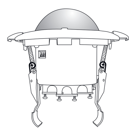
2a. Installation of the LUXOMAT
PD4-M-TRIO-2DALI/DSI-1C-SM
open
C
close
The detector must be in stalled on a solid and
level surface. The circular cover ring must be removed
prior to assembly. To do this, twist the lens (C) anti-
clockwise through approximately 5° and lift off.
Having connected up the wires in accordance with
regulations, secure the detector with 2 screws.
After installation replace the lens and lock (turn
clockwise). Mains to be connected.
5. Position of potentiometer and DIP switch
DIP
123
1
3
2
SM
DIP 1
HA / A
DIP 2
Ini OFF/ON
Lamps at start-up OFF/ON
DIP 3
RESET
Settings by remote control
Resetting
when open:
or
100
1000
All values
which have
or
been pro-
grammed us-
or
ing the remote
control are
deleted, and
those values
which have
been set by
��
��
10
60
to
potentiometer
���
���
are activated.
or
1
to
60
min
min
to
50
1500
Lux
Lux
t < 5 sec.
max
ON
PD4-M-TRIO-2DALI/DSI-1C
2b. Installation of the LUXOMAT
®
PD4-M-TRIO-2DALI/DSI-1C-FC
100 mm
FC
DIP
321
3
2
1
Unlocking device
Sun button – preselected light
value (Daylight operation)
Luminance set point for
constant light regulation
Dimming of the luminance set
point (only for channel 1 and 2)
Saving of the dimmed
luminance set point
Follow-up time light
Fully automatic/semi automatic mode
(only DA1/2) => (see page 2, point 10)
100 h function
=> (see page 2, point 19)
max
Orientation lighting
ON = all LEDs flashes 2x
OFF = all LEDs flashes 1x
ON
Follow-up time
orientation lighting
OFF
Orientation lighting
10 – 30 % of nominal light
DA 1/2 ON/OFF
LED display ON/OFF
Switching between DALI and DSI
(factory settings DALI)
Switching Channel 1C between HVAC-
and light control (factory settings light)
Locking device – Exit
programming mode
LED flashes
Permanent protection against sabotage
3. Hardware configuration
®
Position of light sensors and LEDs
4 5 1
A
A circular opening
of diameter 100 mm
must be produced in
the ceiling.
Having connected
up the cables in
accor dance with
regulations, the
detector is inserted
B
into the opening as
A
Light sensor 1 | B
shown and fixed
1
LED red OFF function
into position with
2
LED green too bright/too dark CDS 1
the retaining bracket
3
LED white semi-automatic DA 1/2
using screws.
4
LED white semi-automatic Channel 3
5
LED green too bright/too dark CDS 2
6
LED red motion indicator/walking test
6. Putting into operation / Settings
Self test cycle
After an initial 60-second self-test cycle, the LUXOMAT
ready for operation.
Potentiometer 3: Follow-up time for light control
45
60
The time can be set infinitely variably at between 1 and 60 minutes. The
30
time-setting is valid for all three channels of the PD4-M-TRIO-2DALI/DSI-1C.
15
TEST
5
1
Symbol TEST: Test mode (Every movement switches on the light for a period
of 2 second, switching it off for a period of 2 seconds after that regardless
of the level of brightness.)
Potentiometer 2: Twilight-switch for light control
1200
The switch-on value for the light can be set at between 40 and 1200 Lux.
600
Using the rotary control, the luminance set points can be set as desired.
200
40
Symbol
: Night-time operation | Symbol
Potentiometer 1: Orientation lighting
ON
60
This rotary controller serves to determine the working time of the orientation
45
lighting (fixed to 20 %).
30
15
5
"ON" for permanent orientation lighting.
OFF
"OFF" for deactiviation of orientation lighting.
Pulse spacing PD-Slave
9s
2s
2 or 9 seconds can be set for the pause between 2 pulses sent to the master.
The setting can be made with activated (
LED ON
For devices with a separate slave input, 2 sec. can be set.
LED OFF
Explanation of the key functions
DA 1/2 ON/OFF when locked
(=> see page 2, point 9)
Dimming when locked
=> (see page 2, point 8)
Activate test mode – when locked
Deactivate test mode: press Reset
Resetting when locked
The lighting relay is switched off, i.e. opened and the follow-up times
reset.
Permanent protection against sabotage
This function blocks the unit permanently (green LED is illuminated).
This operating mode can only be activated during the period of 5
t < 5 sec.
seconds after pressing the "lock" button. This status will only permit
actuating the function "Light on/Light off".
The procedure for leaving this mode is as follows:
using DIP switch 3 or switch the supply voltage as follows:
1sec.
30 sec. - 60 sec.
230 V
50
1500
Lux
Lux
Dimming in opened state
The following approach will prove useful when setting a command value
(example workplace): Place a luxmeter flat on the desk, then, using the
remote control IR-PD4-TRIO-DALI, adjust the light up or down by pressing
the keys "max" or "min" until the desired command value which best
suits your requirements has been reached.
Saving of the through
100 h function in opened state
100
to extend the life span – sums up automatically the burning time of
h
100 % luminosity at the beginning up to 100 hours – only then can
lights dim
Orientation lighting and its follow-up time ON/OFF
Note: During the orientation light phase, the constant light regulation is
also active: if there is sufficient brightness, dimming occurs < 2 V and,
if applicable, the lighting is switched off.
Orientation lighting – Adjustment ot the light intensity
The orientation lighting is adjustable in a span from 10 to 30 % of the
nominal light. Standard adjustment is 20 %.
GB
80 - 90 mm
3 2 6
6
5
4
A
B
3
2
1
SM
FC
Light sensor 2
PD4-M-TRIO-2DALI/DSI-1C is
®
: Daytime/Night-time operation
) or deactivated (
) LED indicator.
reset the hardware
1sec.
ON
OFF
adjusted luminance set point
Advertisement

Subscribe to Our Youtube Channel
Related Manuals for LUXOMAT PD4-M-TRIO-2DALI/DSI-1C-SM


Summary of Contents for LUXOMAT PD4-M-TRIO-2DALI/DSI-1C-SM
- Page 1 5. Position of potentiometer and DIP switch 6. Putting into operation / Settings of the remote control Self test cycle (optional) After an initial 60-second self-test cycle, the LUXOMAT PD4-M-TRIO-2DALI/DSI-1C is ® ready for operation. Remote control Potentiometer 3: Follow-up time for light control The time can be set infinitely variably at between 1 and 60 minutes.
- Page 2 / twice Type of contact: NOC/with pretravel tungsten contact per sec.: Contact load: 3000 W, 230 V~, 16 A cos ϕ=1 / In case the sensing area of the LUXOMAT PD4-M-TRIO- ® - Double locked 1500 VA cos ϕ= 0,5, μ-Contact 2DALI/DSI-1C is too large or areas are being covered that light up for 2 sec.:...
Need help?
Do you have a question about the PD4-M-TRIO-2DALI/DSI-1C-SM and is the answer not in the manual?
Questions and answers