
Related Manuals for Quectel LTE OPEN EVB


Summary of Contents for Quectel LTE OPEN EVB
- Page 1 LTE OPEN EVB User Guide LTE Module Series Rev. LTE_OPEN_EVB_User_Guide_V1.1 Date: 2018-03-19 Status: Released www.quectel.com...
- Page 2 QUECTEL OFFERS THE INFORMATION AS A SERVICE TO ITS CUSTOMERS. THE INFORMATION PROVIDED IS BASED UPON CUSTOMERS’ REQUIREMENTS. QUECTEL MAKES EVERY EFFORT TO ENSURE THE QUALITY OF THE INFORMATION IT MAKES AVAILABLE. QUECTEL DOES NOT MAKE ANY WARRANTY AS TO THE INFORMATION CONTAINED HEREIN, AND DOES NOT ACCEPT ANY LIABILITY FOR ANY INJURY, LOSS OR DAMAGE OF ANY KIND INCURRED BY USE OF OR RELIANCE UPON THE INFORMATION.
-
Page 3: About The Document
LTE Module Series LTE OPEN EVB User Guide About the Document History Revision Date Author Description Woody WU/ 2017-12-29 Initial Lorry XU Updated the GPIO List for AG35-QuecOpen 2018-03-19 Eden LIU module (Table 27). LTE_OPEN_EVB_User_Guide 2 / 62... -
Page 4: Table Of Contents
Applicable Modules ....................... 10 2.2. Key Features ......................... 11 2.3. Interface Overview......................... 13 2.4. Top View of LTE OPEN EVB ....................16 EVB Kit Accessories Assembly ....................... 17 3.1. EVB Kit ..........................17 3.2. EVB Kit Accessories ......................18 Interface Applications ........................20 4.1. - Page 5 LTE Module Series LTE OPEN EVB User Guide 5.2.1. Communication via USB Interface ................. 57 5.2.2. Communication via UART Interface ................58 5.3. Firmware Upgrade ......................... 59 5.4. Reset Modules ........................59 5.5. Power off Modules ......................... 60 5.5.1. Power off LTE-QuecOpen modules ................60 5.5.2.
- Page 6 LTE Module Series LTE OPEN EVB User Guide Table Index TABLE 1: KEY FEATURES OF LTE OPEN EVB....................11 TABLE 2: INTERFACES OF LTE OPEN EVB ....................13 TABLE 3: ACCESSORIES LIST ........................18 TABLE 4: S0201 FUNCTION..........................24 TABLE 5: S1001 FUNCTION..........................24 TABLE 6: WI-FI &...
- Page 7 FIGURE 2: LTE OPEN EVB TOP VIEW ......................16 FIGURE 3: LTE OPEN EVB KIT ........................17 FIGURE 4: EVB KIT ACCESSORIES ....................... 18 FIGURE 5: POWER SUPPLY SCHEMATIC FOR LTE OPEN EVB ..............21 FIGURE 6: POWER INTERFACES ........................21 FIGURE 7: POWER PLUG DESIGN ......................... 21 FIGURE 8: CONNECTION BETWEEN LTE-QUECOPEN TE-A AND EVB ............
- Page 8 LTE Module Series LTE OPEN EVB User Guide FIGURE 42: STATUS INDICATION LEDS ......................45 FIGURE 43: GPIO JUMPERS J0201 AND J0202 ..................... 46 FIGURE 44: TEST POINT J1004/J1005/J1006 ....................50 FIGURE 45: TEST POINT J1003/J0505/J1007/J10204/J0203 ................. 51 FIGURE 46: USB PORTS ..........................57 FIGURE 47: COM PORT SETTING FIELD ON QCOM (USB AT PORT CONNECTION) ........
-
Page 9: Introduction
LTE OPEN EVB User Guide Introduction This document describes how to use the evaluation board (LTE OPEN EVB) of Quectel LTE-QuecOpen and Wi-Fi modules. It is an assistant tool for engineers to develop and test Quectel LTE-QuecOpen and Wi-Fi modules. 1.1. Safety Information The following safety precautions must be observed during all phases of the operation, such as usage, service or repair of any cellular terminal or mobile incorporating Quectel LTE-QuecOpen and Wi-Fi modules. - Page 10 LTE Module Series LTE OPEN EVB User Guide Your cellular terminal or mobile contains a transmitter and receiver. When it is ON, it receives and transmits radio frequency energy. RF interference can occur if it is used close to TV set, radio, computer or other electric equipment.
-
Page 11: General Overview
LTE Module Series LTE OPEN EVB User Guide General Overview The LTE OPEN EVB is designed for developers to develop applications based on Quectel LTE-QuecOpen modules. 2.1. Applicable Modules The EVB can test basic functionalities of the following modules: LTE-QuecOpen modules: ... -
Page 12: Key Features
LTE Module Series LTE OPEN EVB User Guide 2.2. Key Features The following table describes the detailed features of LTE OPEN EVB. Table 1: Key Features of LTE OPEN EVB Features Implementation DC power supply (J0301 or J0601): 4.5V~5.5V, typically 5.0V... - Page 13 Size: 200.0mm × 145.0mm × 1.6mm NOTES VBAT (T0104) is a test point on LTE OPEN EVB, and is used to test the current of the modules. If it is used to supply power for the modules, then R0106 should be disconnected.
-
Page 14: Interface Overview
PWRKEY RESET Micro-USB S0402 S0403 J0802 J0301 J0601 J0801 200mm Figure 1: LTE OPEN EVB Interface Overview Table 2: Interfaces of LTE OPEN EVB Interface Reference No. Description J0301 The power jack on the EVB (bottom side) Typical supply voltage: +5V ... - Page 15 LTE Module Series LTE OPEN EVB User Guide modules, then R0106 must be disconnected Micro-B USB J0601 USB device interface Interface Power Switch S0301 VBAT ON/OFF control Power key (push button), used to turn on/off LTE-QuecOpen S0403 modules PWRKEY J0401...
- Page 16 LTE Module Series LTE OPEN EVB User Guide J0501 Debug UART port (bottom side) UART J0502 Main UART port Interfaces (bottom side) J0503 UART1 port (bottom side) D0310: VBAT ON/OFF indicator D0311: power ON/OFF status indicator LTE-QuecOpen modules D0310, D0311, ...
-
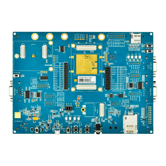
Page 17: Top View Of Lte Open Evb
LTE Module Series LTE OPEN EVB User Guide 2.4. Top View of LTE OPEN EVB The top view of LTE OPEN EVB is shown as following figure. Figure 2: LTE OPEN EVB Top View LTE_OPEN_EVB_User_Guide 16 / 62... -
Page 18: Evb Kit Accessories Assembly
LTE Module Series LTE OPEN EVB User Guide EVB Kit Accessories Assembly 3.1. EVB Kit Figure 3: LTE OPEN EVB Kit LTE_OPEN_EVB_User_Guide 17 / 62... -
Page 19: Evb Kit Accessories
LTE Module Series LTE OPEN EVB User Guide 3.2. EVB Kit Accessories All accessories of LTE OPEN EVB kit are listed as below. USB driver disk USB to RS-232 converter cable and driver disk Wi-Fi antenna Bolts and Micro-USB cable... - Page 20 LTE Module Series LTE OPEN EVB User Guide Wi-Fi antenna Audio Earphone Disks USB 2.0 to RS-232 driver and USB driver disk Codec Boards ALC5616 and TLV320AIC3104 codec boards Others Bolts and coupling nuts for assembling EVB A sheet of paper giving instructions for EVB Instruction Sheet connection, details of EVB accessories, etc.
-
Page 21: Interface Applications
LTE OPEN EVB. 4.1. Power Interfaces (J0301/J0601) The LTE OPEN EVB can be powered by an external power adapter through connecting with the power jack (J0301) or Micro-USB receptacle (J0601) on the EVB. The power adapter connects to a step-down converter which can provide the supply voltage (VBAT) required for operating the EVB and the module. -
Page 22: Figure 5: Power Supply Schematic For Lte Open Evb
Figure 6: Power Interfaces Before connecting the power supply, customers have to select a proper DC power adapter to supply power for the LTE OPEN EVB, and the power plug design of the adapter is shown as below. Inner contact... -
Page 23: Lte-Quecopen Te-A Interface
LTE Module Series LTE OPEN EVB User Guide 4.2. LTE-QuecOpen TE-A Interface The interface is designed to accommodate the TE-A of LTE-QuecOpen modules. The TE-A is connected to the EVB via BTB connectors J0101 and J0102. The interface allows customers to easily test the functionalities of LTE-QuecOpen modules or to develop applications based on these modules. -
Page 24: Figure 9: Simplified Fc20-Te-A/Af20-Te-A Interface Schematic
LTE Module Series LTE OPEN EVB User Guide SGMII_RX_M SGMII_RX_M SGMII_RX_P SGMII_RX_P SGMII_TX_M SGMII_TX_M SGMII_TX_P SGMII_TX_P SGMII_MDIO_DAT SGMII_MDIO_DAT SGMII_MDIO_CLK SGMII_MDIO_CLK SGMII_RST_N SGMII_RST_N SGMII_INT_N SGMII_INT_N SDIO_CMD SDIO_CMD SDIO_CLK SDIO_CLK SDIO_D0 SDIO_D0 SDIO_D1 SDIO_D1 SDIO_D2 SDIO_D2 SDIO_D3 SDIO_D3 VDD_3V3 VDD_1V8 J1002 J1001... -
Page 25: Table 4: S0201 Function
LTE Module Series LTE OPEN EVB User Guide Table 4: S0201 Function Switched Direction Description Left Enable GPIO function Right Enable Wi-Fi function Table 5: S1001 Function Switched Direction Description Left PCM used for BT Right PCM used for codec... -
Page 26: Usb Interface (J0601)
GPIO_27 4.4. USB Interface (J0601) Quectel LTE-QuecOpen modules provide a USB interface which complies with USB 2.0 specifications. USB 2.0 supports high-speed (480Mbps), full-speed (12Mbps) and low-speed (1.5Mbps) modes. The interface is used for AT command communication, data transmission, firmware upgrade and GNSS NEMA output. -
Page 27: Audio Interfaces
LTE Module Series LTE OPEN EVB User Guide LTE OPEN EVB provides a Micro-USB interface J0601 for connection with a host device. The USB data lines USB_DP and USB_DM are connected directly to the LTE-QuecOpen modules. The USB_VBUS line can be used for USB connection detection and EVB power supply. -
Page 28: Table 7: Codec Function Gpio Configuration
LTE Module Series LTE OPEN EVB User Guide J0804 Codec board Figure 14: Connection between Codec Board and EVB If digital audio codec board is intended to be used, then please switch S1001 to the right and short signals illustrated in the figure and table below with the jumper cap. -
Page 29: Analog Audio Interfaces (J0805/J0801/J0802)
LTE Module Series LTE OPEN EVB User Guide 4.5.2. Analog Audio Interfaces (J0805/J0801/J0802) 4.5.2.1. Loudspeaker Interface (J0805) Audio interface J0805 is designed for loudspeakers and the following figure shows a reference design of loudspeaker with an external Class-D audio amplifier. If loudspeaker function is intended to be used, please insert the jumper cap on J0803. -
Page 30: Table 8: Pin Definition Of J0802
LTE Module Series LTE OPEN EVB User Guide The figure and table below illustrate the pin assignment and pin definition of earphone interface J0802. Figure 18: Pin Assignment of J0802 Table 8: Pin Definition of J0802 Pin No. Pin Name... -
Page 31: Handset Interface (J0801)
LTE Module Series LTE OPEN EVB User Guide The following figure shows the sketch design of audio plug which suits for the audio jack on LTE OPEN EVB. SPK_L 32Ω SPK_R 32Ω Figure 19: Sketch of Audio Plug 4.5.2.3. Handset Interface (J0801) Audio interface J0801 is designed for handsets. -
Page 32: U(Sim) Interface (J0901)
Positive microphone input 4.6. U(SIM) Interface (J0901) LTE OPEN EVB has two 6-pin push-push type U(SIM) card (3.0V or 1.8V) connectors J0901 and J0902, and J0902 is reserved for future use. The following figure shows the simplified interface schematic for J0901. -
Page 33: Table 10: Pin Definition Of J0901
LTE Module Series LTE OPEN EVB User Guide Push-Push USIM_VDD USIM_VDD USIM_DATA USIM_DATA USIM_CLK USIM_CLK USIM_RST USIM_RST USIM_PRESENCE USIM_PRE. USIM_GND U(SIM) card connector J0101 J0901 Figure 22: Simplified Interface Schematic for U(SIM) Card Connector J0901 The figure and table below illustrate the pin assignment and pin definition of J0901. -
Page 34: Sd Card Interfaces & Emmc (J0701/J0702 & U0702)
4.7. SD Card Interfaces & eMMC (J0701/J0702 & U0702) LTE OPEN EVB provides two SD card interfaces (J0701 and J0702), which can be used for micro SD cards and standard SD cards respectively. These two interfaces support maximally 32GB and cannot be used simultaneously. -
Page 35: Figure 25: Simplified Interface Schematic For Sd Card Interface J0701, J0702
LTE Module Series LTE OPEN EVB User Guide The following figure shows the simplified interface schematic for J0701, J0702 and U0702. J0101 U0701 J0701 Analog switch SD card SDIO SDC2 connector J0702 SDIO SD card S0701 connector J0201 U0702 SDIO... -
Page 36: Table 12: Pin Definition Of J0701
LTE Module Series LTE OPEN EVB User Guide Figure 28: eMMC Device Table 12: Pin Definition of J0701 Pin No. Signal Name Function DAT2 SDIO data line 2 CD/DAT3 Card detect/SDIO data line 3 SDIO command line Supply voltage SDIO clock... -
Page 37: Table 13: Pin Definition Of J0702
LTE Module Series LTE OPEN EVB User Guide Table 13: Pin Definition of J0702 Pin No. Signal Name Function CD/DAT3 Card detect/SDIO data line 3 SDIO command line Power supply GND Supply voltage SDIO clock VSS2 Power supply GND DAT0... -
Page 38: Table 15: Sd Card Function Gpio Configuration
LTE Module Series LTE OPEN EVB User Guide Figure 29: SD Card Function GPIO Configuration Table 15: SD Card Function GPIO Configuration Pin No. Pin Name Operation Pin No. Pin Name Pin 37 (J0201) SD_INS_DET Shorted to Pin 38 (J0201) -
Page 39: Uart Interfaces (J0501/J0502/J0503)
EMMC_RSTN Shorted to Pin 38 (J0201) GPIO_26 4.8. UART Interfaces (J0501/J0502/J0503) LTE OPEN EVB offers three UART interfaces: COM (DEBUG) J0501, COM3 (MAIN) J0502 and COM (UART1) J0503. J0501 can be used for Linux console and log output. ... -
Page 40: Table 17: Pin Definition Of J0501
LTE Module Series LTE OPEN EVB User Guide The pin assignment and pin definition of J0501/J0502/J0503 are illustrated below. Figure 32: Pin Assignment of J0501 Table 17: Pin Definition of J0501 Pin No. Signal Name Description 1, 6, 7, 8, 9... -
Page 41: Table 18: Pin Definition Of J0502
LTE Module Series LTE OPEN EVB User Guide Table 18: Pin Definition of J0502 Pin No. Signal Name Description Not connected RS232_RXD Receive data RS232_TXD Transmit data RS232_DTR Data terminal ready RS232_GND Not connected RS232_RTS Request to send RS232_CTS Clear to send... -
Page 42: Table 20: Com (Main) & Com (Uart1) Function Gpio Configuration
LTE Module Series LTE OPEN EVB User Guide Not connected RS232_GND Not connected RS232_RTS Request to send RS232_CTS Clear to send Not connected If COM (MAIN) and COM (UART1) functions are intended to be used, then please short the signals illustrated in the figure and table below. -
Page 43: Spi Flash (U0601)
GPIO_5 4.9. SPI Flash (U0601) LTE OPEN EVB includes one SPI Flash device (U0601), as shown in the following figure. Figure 36: SPI Flash Device If the function is intended to be used, then please short the signals illustrated in the figure and table below. -
Page 44: Eeprom (U0903)
GPIO_23 4.10. EEPROM (U0903) LTE OPEN EVB includes one EEPROM device (U0903), as shown in the following figure. Figure 38: EEPROM Device If the function is intended to be used, then please short the signals illustrated in the figure and table below. -
Page 45: Switches And Buttons
I2C_SCA Shorted to Pin 16 (J0201) GPIO_7 4.11. Switches and Buttons LTE OPEN EVB includes five switches (S0201, S0301, S0401, S1001 and S0701) and two buttons (S0402 and S0403), as shown in the following figures. S1001 S0201 S0701 Figure 40: S0201/S0701/S1001 Switch... -
Page 46: Status Indicators
Reset button (push button), used to reset LTE-QuecOpen modules 4.12. Status Indicators LTE OPEN EVB provides 8 status indicators: D0310, D0311, D0312, D0313, D0201, D0202, D0203 and D0204. The following figure shows the location of these LED indicators. D0204 D0203 D0202 D0201... -
Page 47: Gpio Interfaces
LTE Module Series LTE OPEN EVB User Guide Table 24: Description of Status Indication LEDs Reference No. Description VBAT ON/OFF indicator. D0310 Bright: VBAT ON Extinct: VBAT OFF Power ON/OFF indicator for LTE-QuecOpen modules D0311 Bright: the module is powered on... -
Page 48: Table 26: Pin Definition Of J0201
LTE Module Series LTE OPEN EVB User Guide COEX_UART_RX GPIO_37 WLAN_EN GPIO_38 WAKE_WLAN GPIO_59 PCM_SYNC GPIO_79 PCM_CLK GPIO_78 PCM_OUT GPIO_77 PCM_IN GPIO_76 MAIN_CTS GPIO_3 MAIN_RTS GPIO_2 MAIN_RXD GPIO_1 MAIN_TXD GPIO_0 USIM1_PRESENCE GPIO_34 VDD_1V8 VDD_1V8 Table 26: Pin Definition of J0201 Pin No. -
Page 49: Table 27: Gpio List For Ag35-Quecopen Module
GPIO_20 SPI_MOSI The name of the GPIO pins on LTE OPEN EVB are defined based on EC2x-QuecOpen modules. The pin assignment of AG35-QuecOpen and BG96-QuecOpen modules differs from that of EC2x-QuecOpen modules. The following table lists the detailed GPIO number on AG35-QuecOpen module. - Page 50 LTE Module Series LTE OPEN EVB User Guide PCM_SYNC GPIO_79 GPIO_79 (J0202) PCM_IN GPIO_76 GPIO_76 (J0202) PCM_CLK GPIO_78 GPIO_78 (J0202) PCM_OUT GPIO_77 GPIO_77 (J0202) I2C2_SDA GPIO_6 R0922 I2C2_SCL GPIO_7 R0921 SPI_MOSI GPIO_20 SPI_MOSI_AG35 (J1005) SPI_MISO GPIO_21 SPI_MISO_AG35 (J1005) SPI_CS_N GPIO_22...
-
Page 51: Test Points
J0201/J0202 to J0204 pin 1 (VDD_1V8) or pin 6 (GND). 4.14. Test Points LTE OPEN EVB provides a series of test points. They can help customers to obtain the corresponding waveform of some signals. The following two figures show test points J1003, J1004, J1005, J1006, J0505, J1007, J0203 and J0204. -
Page 52: Table 28: Pin Definition Of Test Points
LTE Module Series LTE OPEN EVB User Guide J0203 J1003 J0204 J0505 J1007 Figure 45: Test Point J1003/J0505/J1007/J10204/J0203 Table 28: Pin Definition of Test Points J0203 Pin No. Pin Name Description GPIO1 GPIO2 GPIO3 Connect directly to LTE-QuecOpen modules GPIO4... - Page 53 LTE Module Series LTE OPEN EVB User Guide GPIO_14 GPIO_15 GPIO_16 GPIO_17 GPIO_18 Reserved GPIO_19 Reserved GRFC1 Reserved GRFC2 Reserved J0203 Pin No. Pin Name Description VDD_1V8 1.8V power supply from U0401 LED1 LED2 Can be connected to any GPIO.
- Page 54 LTE Module Series LTE OPEN EVB User Guide Pin No. Pin Name Description VDD_3.3V 3.3V power supply from U0402 Connected to J0202 pin 19 with analog switch U1001. PCM_SYNC If this function is intended to be used, S1001 should be switched to the right.
- Page 55 LTE Module Series LTE OPEN EVB User Guide modules can be controlled by PC DTR. When DTR is at high level, RESET will be pulled down to reset the module. USB_VBUS enable pin. Connect it to DTR_TEST pin, and then USB_VBUS of VBUS_TEST LTE-QuecOpen modules can be controlled by PC DTR.
- Page 56 LTE Module Series LTE OPEN EVB User Guide MAIN_TXD_1.8V MAIN_TXD_1.8V VDD_1V8 1.8V power supply from U0401 J1007 Pin No. Pin Name Description UART1_RTS_3.0V UART1_RTS_1.8V UART1_RXD_3.0V UART1_RXD_1.8V Used for test UART1_CTS_3.0V UART1_CTS_1.8V UART1_TXD_3.0V UART1_TXD_1.8V VDD_1V8 1.8V power supply from U0401 LTE_OPEN_EVB_User_Guide...
-
Page 57: Operation Procedures Illustration
LTE Module Series LTE OPEN EVB User Guide Operation Procedures Illustration This chapter introduces how to use LTE OPEN EVB for testing and evaluation of Quectel LTE-QuecOpen and Wi-Fi modules. 5.1. Power on Modules 5.1.1. Power on LTE-QuecOpen Modules 1. Connect the TE-A of respective modules to the EVB via connectors J0101 and J0102. -
Page 58: Communication Via Usb Or Uart Interface
Figure 46: USB Ports 3. Install and then use the QCOM tool provided by Quectel to realize the communication between the module and the PC. The following figure shows the COM Port Setting field on QCOM: select correct “COM port” (USB AT Port which is shown in above figure) and set correct “Baudrate” (such as 115200bps). -
Page 59: Communication Via Uart Interface
USB serial port number can be checked through the PC Device Manager, as shown below. Figure 48: USB Serial Port Install and then use the QCOM tool provided by Quectel to realize the communication between the module and the PC. The following figure shows the COM Port Setting field on QCOM: select correct “COM port”... -
Page 60: Firmware Upgrade
LTE OPEN EVB User Guide 5.3. Firmware Upgrade The firmware of Quectel LTE-QuecOpen modules is upgraded via USB port by default. Please follow the procedures below to upgrade firmware. Install and open the firmware upgrade tool QFlash on PC and then power on the LTE-QuecOpen modules according to the procedures mentioned in Chapter 5.1.1. -
Page 61: Power Off Modules
LTE Module Series LTE OPEN EVB User Guide 5.5. Power off Modules 5.5.1. Power off LTE-QuecOpen modules There are two ways to power off LTE-QuecOpen modules. One way is to execute AT+QPOWD command, and this is the best and the safest way. The module will log off from the network and save data before shutdown, but it will be powered on again after shutdown. -
Page 62: Appendix A References
LTE Module Series LTE OPEN EVB User Guide Appendix A References Table 30: Related Documents Document Name Remark Quectel_LTE_Windows_USB_Drivers_Installation_ Windows USB driver installation guide Guide for EC2x, BG96 and AG35 modules Respective hardware design Quectel_xx_Hardware_Design EC2x/BG96/AG35-QuecOpen modules Quectel_FC20_Series_Hardware_Design FC20 series hardware design... - Page 63 LTE Module Series LTE OPEN EVB User Guide Input/Output Light Emitting Diode Long Term Evolution Microphone Not Connected Private Computer Printed Circuit Board Pulse Code Modulation Power Output Radio Frequency Secure Digital UART Universal Asynchronous Receiver & Transmitter UMTS Universal Mobile Telecommunications System...
Need help?
Do you have a question about the LTE OPEN EVB and is the answer not in the manual?
Questions and answers