
Summary of Contents for GE Grid Solutions MDS Master Station
- Page 1 MDS™ Master Station Modular Communications Platform MDS 05-6399A01, Rev. F DECEMBER 2016 Firmware Version 4.1.6 and higher.
- Page 3 Quick-Start instructions for this product are contained in publication 05-6398A01. Visit our website for downloadable copies of all documentation at www.gemds.com. IMPORTANT This manual describes the details, installation, configuration and operation of the MDS™ Master Station. It does not cover the description or configuration of features and settings common to the MDS Orbit family of products.
-
Page 5: Table Of Contents
TABLE OF CONTENTS INTRODUCTION ..................... 9 1.1 Organization of Manual....................9 Related Publications ....................10 KEY PRODUCT FEATURES................11 2.1 Accessories and Spare Items ................... 13 2.2 FCC Emission Designators: How to Find Them ............15 2.3 Front Panel ........................ 15 2.4 Rear Antenna Connections .................. - Page 6 CLI Quick Reference Table ................... 30 5.4 Interface Naming....................... 32 5.5 Configuration via the Device Manager ..............32 General Configuration ................... 33 5.6 Interface Configuration ..................... 34 Understanding ....................... 34 Configuring ......................34 5.7 LAN..........................38 Understanding ....................... 38 Configuring ......................38 5.8 Bridging ........................
- Page 7 Technical Specifications ..................103 6.5 LN Radio Modules ....................105 LN Master Radio Module LED Indicators ............105 Technical Specifications ..................106 6.6 Alarm and Alarm/Relay Modules ................109 Alarm Module LEDs .................... 110 Alarm/Audio Interface ..................110 Alarm/Relay Toggle Switch (6847 Only) ............. 111 Alarm/Relay RF Connections (6847 Only) ............
-
Page 8: Copyright Notice
Copyright Notice This Technical Manual and all software described herein are protected by copyright: 2015 GE MDS. All rights reserved. GE MDS reserves its right to correct any errors and omissions in this publication. Safety words and definitions The following symbols used in this document indicate the following conditions: Indicates a hazardous situation which, if not avoided, will result in death or serious injury. - Page 9 The RF safety distance is calculated based on each product type’s highest output power configuration with no duplexer, redundant switching, or cable losses. Table 1-1 Antenna Gain vs. Minimum RF Safety Distance Antenna Gain Radio Module Equipped 0–5 dBi 5–10 dBi 10–16.5 dBi SDM4 –...
- Page 10 The AC socket outlet shall be installed near the equipment and shall be easily accessible. 7. The power supply cord must be disconnected from the appliance inlet before removing any power supply from the chassis. 8. CAUTION: THIS UNIT HAS MORE THAN ONE POWER SUPPLY CORD.
- Page 11 Environmental Information The equipment that you purchased has required the extraction and use of natural resources for its production. Improper disposal may contaminate the environment and present a health risk due to hazardous substances contained within. To avoid dissemination of these substances into our environment, and to diminish the demand on natural resources, we encourage you to use the appropriate recycling systems for disposal.
- Page 12 and GE makes no representations or warranties for the use of this code by you independent of any GE provided software or services. For more information, contact gemds.techsupport@ge.com. MDS™ Master Station MDS 05-6399A01, Rev. F...
-
Page 13: Introduction
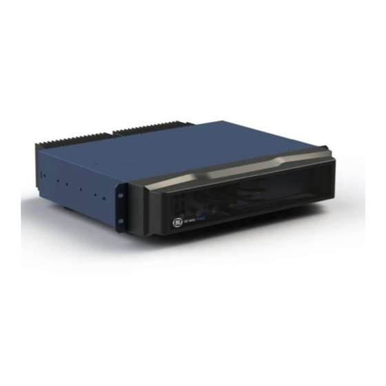
1.0 INTRODUCTION The MDS™ Master Station is an advanced, flexible platform designed for the demanding requirements of today’s industrial wireless networks. It represents the latest development in a line of MDS products that set the standards for wireless performance today. The Master Station builds on this legacy with several innovative features, including a single compact chassis (2 RU), 100% duty cycle operation (no cooling fans required), front panel access to all modules, and drop-in compatibility with earlier MDS x790/x710 radio systems. -
Page 14: Related Publications
Related Publications In addition to this manual, a companion Setup Guide is available for the MDS™ Master Station, Part No. 05-6398A01. The Setup Guide is focused on the essential steps for installation and startup of the unit, and is designed to be used with this Technical Manual. The MDS™... -
Page 15: Key Product Features
2.0 KEY PRODUCT FEATURES As a licensed, long range IP/Ethernet and serial communications device, the Master Station exceeds industry standards for reliability and performance in wireless networks. Listed below are several key features and benefits of the product, and these are available with the appropriate modules installed and configured in the chassis. - Page 16 When equipped with LN radio cards, the Master Station works with Orbit MCR LN (left) and Orbit ECR LN (right. Figure 2-2 MPRS Compatible Remotes When equipped with SD radio cards, the Master Station works with legacy MDS x710 (left), and newer MDS SD Transceivers.
-
Page 17: Accessories And Spare Items
2.1 Accessories and Spare Items The following table lists common accessories and spare items for use with the Master Station. GE MDS also offers an Accessories Selection Guide listing an array of additional items available for use with the product. Contact your factory representative or visit www.gemds.com to obtain a copy of the guide. - Page 18 Alarm/Relay Module Non-Redundant Alarm Non-redundant—alarm and audio interface. 03-6848A01 Module Spare duplexer in tray wired for MDS Master Station. 900MHz Duplexers (TX HIGH) 9 MHz RX 932.0-932.5, TX 941.0-941.5), COMBINED OUT 03-6837D9B1 24 MHz RX 928.0-929.0, TX 952.0-953.0), COMBINED OUT 03-6837D9C1 31 MHz RX 928.0-929.0, TX 959.0-960.0), COMBINED OUT...
-
Page 19: Fcc Emission Designators: How To Find Them
2.2 FCC Emission Designators: How to Find Them An FCC emission designator is a seven-character string that represents the bandwidth, modulation, and other characteristics of a transmitted radio signal. This information is required when applying for an FCC license. The designator assigned to your equipment depends on the particular sub-model of the product line you are licensing. -
Page 20: Rear Antenna Connections
of the Alarm/Relay module will be installed. The table that follows lists the module types available. Table 2-2. Module Descriptions Module Name Function Power Supply 1 6843: (+/- 12-36 VDC) Provides operating power based on a variety of AC and DC input options. -
Page 21: Installation Planning
3.0 INSTALLATION PLANNING This section covers pre-installation factors that should be considered when installing the Master Station. Careful planning will help achieve optimal performance from the radio. After reviewing this section, refer to the step-by-step installation procedures beginning on Page 23. The specific details at an installation site may vary, but there are three main requirements for installing the unit in all cases: •... -
Page 22: Repeater And Polling Remote Operation (Mprs Only)
provides communications between a central host computer and remote terminal units (RTUs) or other data collection devices. In such an arrangement, the operation of the radio system is transparent to the computer equipment. Repeater and Polling Remote Operation (MPRS Only) In a system using FCC Part 90 repeater and polling remote, the polling remote radio operates in half-duplex mode and the repeater operates in half-duplex or full-duplex mode. -
Page 23: Redundant Versus Non-Redundant Operation
all of the “node” radios downstream. Passive polling allows monitoring without interrupting payload data transmission. In order for PulseNET to discover SD Master Stations in the network, DLINK must be enabled and properly configured. Refer to the section “Dlink” on Page 48 for information on how to configure DLINK. -
Page 24: Grounding Considerations
Table 3-1. Signal Loss in Coaxial Cables (at 900 MHz) 10 Feet 50 Feet 100 Feet 200 Feet Cable Type (3 Meters) (15 Meters) (30.5 (61 Meters) Meters) 0.85 dB 4.27 dB 8.54 dB 17.08 dB RG-8A/U 0.23 dB 1.15 dB 2.29 dB 4.58 dB 1/2 inch HELIAX... -
Page 25: Data Interface Connections
3.6 Data Interface Connections Ethernet Data Interface (RJ-45) The Ethernet interface supports both radio management and payload data transport functions. For radio management, connecting via a web browser provides enhanced functionality and ease- of-use over serial/USB methods. Web-based management is the preferred and primary means of accessing the transceiver through the built-in Device Manager. -
Page 26: Mini Usb
Table 3-4. RF-45 to DB-9F Pin Out Signal RJ-45 DB-9F Standard RS-232 Ground Ground No connection N.C. Mini USB The Mini USB port can be used to management the radio through a scriptable command line interface (CLI) using the proper USB drivers available at www.gemds.com. Connect to the management PC using the included Mini USB Cable. -
Page 27: Installation Procedures
4.0 INSTALLATION PROCEDURES This section presents the steps necessary for installing the radio and connecting it to associated equipment. After completing these steps, the radio is ready for in-service operation. 4.1 Unpacking and Inspection Check the contents against the packing list secured to the outside of the shipping box. Accessories and spare parts kits, if any, are wrapped separately. - Page 28 Figure 4-1. Internal Duplexer, Triple N connectors Figure 4-2. Internal Duplexer (or internal T/R switch), Single N connector Figure 4-3 External duplexer or dual antennas, Double C connectors (TX and RX ports pass directly through) 4. Install the Data Interface Cabling. Interface connections are made to the front of the Platform Manager module.
- Page 29 - Serial Data—Attach data equipment to the front panel COM1 and/or COM2 ports. The unit is hardwired as a DCE device (DB9-F to RJ-45 connector, GE MDS part no. 73-2434A25). - Ethernet LAN—Attach data equipment to the ETH1 and/or ETH2 port. The auto-sensing MDIX feature allows either a straight-through or crossover cable to be used.
-
Page 30: Initial Startup & Operation
Figure 4-4 DC Power Connector 6. Connect a PC for Configuration (LAN or USB port). This prepares the Master Station for programming of desired operating parameters. Configuration is further described in Section 5.0 Device Management If serial-based cabling is used for configuration, an adapter may be required at the PC, as many PCs do not offer a serial port. -
Page 31: Normal Indications
PWR ALARM PWR /ALARM ACTIVE WiF i TX/RX 6834 Figure 4-5 LED Indicators Normal Indications When power is first applied, the following events occur in a normally working unit: • All front panel indicators light briefly • for the selected transceiver board lights. ACTIVE LED •... -
Page 32: Device Management
5.0 DEVICE MANAGEMENT This section describes the steps for connecting a PC, logging in, and setting unit parameters. The focus here is on the local serial/USB console interface, but other methods of connection are available and offer similar capabilities. The key differences are with initial access and appearance of data. -
Page 33: Creating A One-Time Password
A one-time recovery password is different from the one used to log into the unit on a routine basis. It is only for use when the primary password is lost or forgotten. When a one-time password is used to log in, that password is automatically revoked from the list of passwords created. -
Page 34: Configuration Via Command Line (Cli)
The current list of passwords may be viewed by issuing the command show system recovery one- . The following is an example output from that command. On the unit shown, only time-passwords two passwords have been stored. Password 1 or 2 can be deleted from this list. IDENTIFIER FUNCTION STATUS DATE CREATED DATE REVOKED USER... - Page 35 Table 5-1. CLI Quick Reference Table If you wish to... Enter this CLI command: Create a bridge % set interfaces interface bridge type bridge Add the ETH1 interface to a % set interfaces interface bridge bridge-settings members port eth-0/0/0 bridge Remove the ETH1 interface % delete interfaces interface bridge bridge-settings members port eth- from a bridge...
-
Page 36: Interface Naming
Table 5-1. CLI Quick Reference Table If you wish to... Enter this CLI command: Reboot device to firmware > request system power restart inactive inactive image 5.4 Interface Naming Interface naming of physical devices on the MDS™ Master Station uses the following format: <type>-<slot>/0/<port>... -
Page 37: General Configuration
services web http(s) enabled true/false General Configuration For initial configuration of the Master Station, perform the following steps: 1. Connect the unit to a PC via an Ethernet connection. 2. Configure your PC network settings to an IP address on the same subnet as the unit. The default subnet mask is 255.255.255.0 For IP addressing the Master Station uses a routing prefix expressed in CIDR notation... -
Page 38: Interface Configuration
• Serial data interface configuration • Encryption settings Similarly Wizards Interface Setup will allow the user to configure the LN radio. 5.6 Interface Configuration Understanding A serial cable (RJ45 cable with proper ETH to DB9 converter) may be used to connect to a COM port on the unit to access the CLI. - Page 39 Clicking on the row of the port you wish to edit will present you with the following options: • Line Mode - Selection of the operation line mode of the serial port. Choices are: - RS232 (DEFAULT) - RS485 - 2 Wire - RS485 - 4 Wire •...
- Page 40 - 7N2 - 7 char bits, no parity, 2 stop bits - 7E2 - 7 char bits, even parity, 2 stop bits - 7O2 - 7 char bits, odd parity, 2 stop bits - 8N1 - 8 char bits, no parity, 1 stop bit (DEFAULT) - 8E1 - 8 char bits, even parity, 1 stop bit - 8O1 - 8 char bits, odd parity, 1 stop bit - 8N2 - 8 char bits, no parity, 2 stop bits...
- Page 41 - The unit shall support flow control (Throttling) on the RTS pin. The device is expected to be wired via null modem to an external DCE device. The CTS line of the external DCE device drives the RTS line of the unit. Statistics for the Serial ports and IP Payload 1, 2, 3 are located under the active SD radio .
-
Page 42: Lan
SD-x/0/0 Interfaces” for more details. 5.7 LAN Understanding This section will cover only the basic configuration of Ethernet ports and bridges. For full details on the configuration of more advanced features, please reference the MDS Orbit MCR Technical Manual (05-6632A01) The Master Station has external Local Area Network (LAN) ports ( ports) that can be ETH1/2... - Page 43 - Eth 100Mb Full • Vlan Mode - Virtual LAN Setting. - None (DEFAULT) - Access - Use this if this interface is intended to be a member of only a single VLAN. - Trunk - Use this if this interface is intended to be a member of multiple VLANs. •...
-
Page 44: Bridging
• Filter Input - Use for selecting and applying a firewall filter (from available filters) to incoming traffic on this interface. • Filter Output - Use for selecting and applying a firewall filter (from available filters) to outgoing traffic on this interface. For more information on packet filtering, refer to “Access Control List (Packet Filtering / Firewall)”... -
Page 45: Configuring
The bridge learns the clients’ locations by analyzing the source address of incoming frames from all attached networks. For example, if a bridge sees a frame arrive on LAN port from Host A, the bridge concludes that Host A can be reached through the segment connected to LAN port. Through this process, the bridge builds a forwarding table (the learning process). - Page 46 Any combination of the three VRC numbers may be entered in the selection fields. Figure 5-2. Virtual Radio Channel (VRC) Concept illustrates the relationship between the VRC settings and the routing of data between units. Figure 5-2. Virtual Radio Channel (VRC) Concept Understanding the use of Media Access Control (MAC) An important feature of the transceiver is Media Access Control (MAC).
-
Page 47: Configuration
overhead is used to accomplish these tasks, which translates to increased bandwidth efficiency of the radio channel with minimal latency, ensuring that messages are delivered in a timely manner. Status Tab The Status tab on the sdms interface page gives an overview of the current state of the sdms interface. -
Page 48: General Settings
Basic Config Tab General Settings The Basic Settings contains important RF and modem selections for radio operation. Members – The Master Station (sdms) interface is a logical interface that is composed of • one or more physical SD interface cards (sd-nic). The ‘members’ configuration item is the mapping between the logical sdms interface, and the physical sd-nic cards. - Page 49 This is factory configured to contain SDM Radio Modules in slot 1 and slot 2 of the Master Station. If the Master Station is a non-redundant system with only 1 Radio Module, this will contain only ‘sd-1/0/0’. Radio Mode – The radio can operate in one of several modes. The available selections •...
- Page 50 Operational Example: SD System “Alpha” has eight units and SD System “Beta” has eight units. A user wishes to occupy frequency 952.1235 MHz on both of these systems. Proper system installation has been adhered to in both networks. System Alpha’s units would all be set to System ID = 1, System Beta's units would be set to System ID = 5.
- Page 51 - None – This is the default value, and is used when the Master Station being configured is not to be used as a repeater in the network. - Repeater – This value should be selected when the Master Station being configured is to be installed as a repeater in the network, and will not have devices connected to it that will be polled, such as attached RTUs.
-
Page 52: Dlink
Table 5-2. Modem Selection vs. Speed, Bandwidth & Sensitivity Approximate Modem Type Over-the-air ETSI B/W (kHz) Sensitivity Selection Speed (bps) Compliance (dBm) BELL 1200 12.5 -110 1200 12.5 -110 1, 2 3200 3200 5.00 -108 4800B 4800 12.5 -110 4800F 4800 6.25 -108... -
Page 53: Mac Settings
Unit – This parameter identifies the radio in the wireless network with a specific ID • during diagnostic sessions. For compatibility with legacy devices, the value must be 10000 or greater (2710 in hexadecimal). Type – This setting identifies the radio as a Node, Root, Repeater, Peer, or Gate. Each of •... - Page 54 Device Type – The role this device will be performing in the network. If this device is • operating as a repeater, the MAC device type MUST be 'remote'. MAC Retries – If a message is not acknowledged after transmission it will be resent. This •...
-
Page 55: Ip Payload
- Peer to Peer Enabled – If enabled, the AP will allow enabled peers to send traffic through the AP to other enabled peers by rebroadcasting their transmissions to all other remotes in the system. - Ethernet Rebroadcast Type – When rebroadcasting peer-to-peer Ethernet traffic, only the selected type of traffic will be rebroadcast to other remotes on the network. - Page 56 TCP Server specific configuration options include: Local IP Port – The TCP port number that the server will listen for connections on. • IPv4 Bind IP – If the Master Station is configured with multiple IP interfaces; you can • specify that the IP Payload service only will listen for connections on one of the IP addresses of the system.
- Page 57 TCP Client specific configuration options include: Server IP Address – The IP address of the server the Master Station is to connect to. • Remote IP Port – The TCP port that the server is listening on. • TCP Server/Client: As the name implies, TCP Server/Client is a combination of the TCP Server mode, and TCP Client mode.
- Page 58 the payload data. When the Master Station receives over-the-air payload data from remote SD radios, the Master Station will establish a UDP connection to the application and transmit the payload data. These connections are not persistent, and as such must be established for each transmission.
- Page 59 Firewall Filter The firewall filtering rules to apply to this interface when it is not a member of a bridge or VLAN interface. For full information on applying firewall filters to interfaces, see the MDS Orbit MCR Technical Manual (05-6632A01). VLAN The VLAN configuration section is used to configure the SDMS interface to be a member of a VLAN.
- Page 60 The NAT configuration section is used to configure network address translation (NAT) on the SDMS interface. For full information on configuring NAT on interfaces, see the MDS Orbit MCR Technical Manual (05-6632A01). MDS™ Master Station MDS 05-6399A01, Rev. F...
-
Page 61: Advanced Configuration
Advanced Configuration Tab Advanced Configuration Soft-Carrier Dekey – Specifies how long (in ms) to wait after the removal of the keying • signal before actually dropping the transmitter’s carrier. The default setting is 0, but it may be set to any value up to 255 ms. In most cases, no change is required from the default setting. - Page 62 - Lo – The PTT line is active-low. Push To Talk Delay – Specifies a brief time delay after a keying event, which must • expire before the radio is allowed to transmit. The allowable range is 0 to 255 ms, with the default being 0.
- Page 63 need to be changed to ‘bypassed’ in order to work with legacy products. It is recommended to leave this value set to ‘auto’ unless there is an explicit need to change it. Rx Mute – The number of milliseconds to mute the receiver after transmitting data. •...
-
Page 64: Audio
Audio Audio settings are only available for configuration when the radio is configured to operate in x710 compatibility mode. Audio Enabled – If enabled, the radio’s transmit functionality will switch to analog • whenever PTT is asserted. Rx Level – Receive audio output level to modem (dBm). Received signal at the peak •... -
Page 65: Actions
Enabled Alarms This configuration section controls which of the various alarms that can be generated on the SD NIC will be propagated up to the platform manager for system logging. All alarms default to being enabled, and should remain enabled unless there is an explicit need to disable one. RTU Simulator The unit’s built-in RTU simulator generates random data similar to what would be supplied by an external RTU connected to the radio. - Page 66 Link Test The primary use of the Link Test is to verify that a specific radio's settings are consistent with the initiator including: Assigned frequency, unit number setting, encryption (if enabled), etc. Also collected at the same time is an indication of link quality. All radios are always ready to respond to a Link Test message.
- Page 67 Perform Failover If the Master Station is equipped with redundant SD radios, the active radio can be manually toggled by selecting the “Perform action” button. The manual toggle-switch on the alarm/relay board must be in the ‘Automatic’ position for this operation to succeed. The toggle-switch will override all software-based control of which radio is active.
- Page 68 Repeater Network Change – Change remote parameters that may need to be configured • when running in a network which uses a MDS™ Master Station as a repeater. Generic Dlink Message – Broadcast a custom Dlink command to all units on the system. •...
-
Page 69: Remote Sd Reprogramming
Remote SD Reprogramming OTA Reprogramming Overview This feature is for reprogramming SD remote radios only. This will not reprogram other Master Stations on the network. The DLink “Root” is the central location from which polling originates. Other locations in the network should be designated as “Nodes”... - Page 70 Channel Usage – Set to either Intrusive or Passive as desired. • - Passive (Non-intrusive) operation “piggy-backs” reprogramming data onto normal payload data streams, thus allowing payload data to continue uninterrupted, but will be slower than intrusive operation. This mode requires payload data to be sent so that the reprogramming data can be carried.
- Page 71 Modem Speed (bps) Approximate Time Required 4800 6 hours 9600 1 hour, 30 minutes 19200 1 hour, 30 minutes Radio assumptions: Signal strength -85 dBm or stronger, Packet Size: 40, Block Size: 512, Retry: 3, Download Delay: Short. Polling assumptions: Serial polling with 1-second poll time, sending random data at 50- 100 bytes.
- Page 72 Port (TFTP) – The TCP port that the TFTP server is operating on. • User Name (SFTP/FTP) – The user to connect to the SFTP/FTP server as. • Password (SFTP/FTP) – The password for the SFTP/FTP server. • Control Port (SFTP/FTP) – The TCP port that the SFTP/FTP server is operating on. •...
-
Page 73: Monitoring
Monitoring Statistics Interfaces sdms Status Statistics Discontinuity Time – The time on the most recent occasion at which any one or more of • this interface’s counters suffered a discontinuity or interruption of service. In Octets – The total number of octets received on the interface, including framing •... -
Page 74: Performance
Performance Interfaces sdms Status Performance Measured RF Power – Read-only indication of the measured RF output power (in dBm). • Signal to Noise (SNR) – Read-only indication of the signal-to-noise ratio of the received • signal. RSSI – Read-only indication of the measured received signal strength (in dBm). •... -
Page 75: Sd-X/0/0 Interfaces
5.10 SD-x/0/0 Interfaces Configuration for each SD Radio Modules is done via the SDMS interface. Each individual interface provides statistics for serial, IP payload and MAC that could be helpful in a debugging situation. General Interfaces sd-x/0/0 Status / General This screen is read-only and displays the status of the SD NIC interface. - Page 76 Com 1 Tx Bytes – The total number of transmitted bytes on the COM1 port. • Com 1 Rx Bytes – The total number of received bytes on the COM1 port. • Com 2 Tx Bytes – The total number of transmitted bytes on the COM2 port. •...
- Page 77 Tx Radio Packets – Total number of transmitted packets through the radio. • Rx Radio Failed Bytes – Total number of received bytes failed through the radio. • Rx Radio Failed Packets – Total number of received packets failed through the radio. •...
-
Page 78: Lnms Interface
MAC Acknowledgements – Total number of MAC frames acknowledged by the access • point. (when operating as a remote) MAC TTL Expirations – Total number of frames dropped due to expired time-to-live • counters. 5.11 LNMS interface Understanding Licensed Narrowband Modules are available in various global frequencies. The term “LN”... - Page 79 The general specifications for all LN NIC modules are: Peak Power Output: 20 dBm to 40 dBm peak power in 1.0 dBm steps (DEFAULT = 40 dBm) Output Impedance: 50 Ohms Antenna Connector: TNC female Modulation Type: QPSK, 16QAM, 64QAM ...
- Page 80 Important Notes and Information Regarding EVM EVM (error vector magnitude) is dependent on the modulation format and should be used as a relative measurement of the link quality. A low EVM value indicates a better link quality than a high value. Algorithmically, using QAM modulation, the transceiver calculates the value by measuring the sample points of each "bit"...
- Page 81 Configuring Basic configuration with defaults Navigate to: Interfaces / lnms ---> Basic Config / LN Radio Figure 5-5. Licensed Narrowband (LN) Configuration Settings Members – The ln-nic interfaces that are used for this configuration Device Mode - Sets the role the radio will assume in the network. Remote (DEFAULT) ...
- Page 82 useful in applications that rely on IP packets with small payloads, such as terminal server operations or MODBUS polling. This setting must match on each radio (Remote and AP). Power - The transmit power of the radio: Valid values: 20 - 40 dBm – DEFAULT is 40dBm ...
- Page 83 Figure 5-6. Licensed Narrowband (LN) PSK Security Settings Figure 5-7. Licensed Narrowband (LN) EAP on remote Security Settings Figure 5-8. Licensed Narrowband (LN) EAP on an access point Security Settings Security Mode - The type of over the air authentication to perform none - Provide no device authentication or data privacy (DEFAULT) psk - Use pre-shared key authentication protocol eap - Use Encapsulated Authentication Protocol - will change the fields displayed and give the...
-
Page 84: Advanced Configuration
Rekey Interval (AP only) – The session key for an active secure link changes at a regular basis. You may increase the length of the rekey interval in order to reduce overhead caused by the rekeying communications between radios on a narrowband channel. Valid values: 0 –... -
Page 85: Monitoring
Remote Age Time – Length of time, in seconds, of inactivity of a remote before it is disconnected. Valid values: 180-4294967295 seconds, DEFAULT = 600 (10 minutes). Endpoint Age Time (AP only) - Length of time in seconds of inactivity on an endpoint before it is removed from the endpoint database. - Page 86 Statistics - A collection of interface-related statistics objects. Figure 5-12. Licensed Narrowband (LN) Statistics Discontinuity Time - The time on the most recent occasion at which one or more of this interface's counters suffered a discontinuity. In Octets - The total number of octets received on the interface, including framing characters. ...
- Page 87 Figure 5-13. Licensed Narrowband (LN) Status The following status items appear on both APs and Remotes (unless stated otherwise) General Init Status - State of the NIC Initialization Off - Not operating Initializing - Powering on the NIC Discovering - Determining the NIC address Reprogramming - Programming the NIC firmware Configuring - Configuring the NIC Complete - Initialization complete...
- Page 88 MAC Tx Retry - Re-transmission count due to previously unsuccessful transmission. MAC Rx Success - Valid packet received. MAC Rx Error – Received packets dropped due to error. Last RX Packet Last RSSI – The RSSI measured at the time of the last received packet. Last Error Vector Magnitude –...
- Page 89 Remote’s AP Info (Remote Only): Figure 5-16. Licensed Narrowband (LN) Remote’s AP Information AP Address - MAC address of access point this device is linked to. IP Address - IP address of access point this device is linked to. ...
-
Page 90: Cli Configuration Examples
station so that RSSI can be checked. While in Test Mode, a radio will not operate normally and does not communicate with the narrowband network. To enter or exit Test Mode, select the desired test state from the State drop-down box and click Perform Action. - Page 91 arp-cache false; qam16-threshold -85; qam64-threshold -70; Security configuration The default security mode, as shown above, is none. The following configures the LN module to use pre-shared key authentication with the passphrase 'mypassphrase' and aes256-ccm encryption. NOTE When viewing the configuration, the passphrase that you entered is not displayed in plaintext. This is a security measure.
- Page 92 power tx-frequency 451.4; rx-frequency 456.4; channel 12.5KHz-9.6ksps; modulation automatic; false; security { security-mode eap; encryption aes256-ccm; radius-server RADIUS_SERVER; advanced-config { data-retries packet-ttl 600; remote-age-time 600; endpoint-age-time 300; allow-retransmit true; arp-cache false; qam16-threshold -85; qam64-threshold -70; Remote Mode The following will configure the LN module as a Remote with the network name of 'MyNetwork' and default settings.
- Page 93 qam16-threshold -85; qam64-threshold -70; Security Configuration The default security mode, as shown above, is none. The following configures the LN module to use pre-shared key authentication with the passphrase “mypassphrase” and aes256-ccm encryption. NOTE When viewing the configuration, the passphrase that you entered is not displayed in plaintext. This is a security measure.
- Page 94 power tx-frequency 456.4; rx-frequency 451.4; channel 12.5KHz-9.6ksps; modulation automatic; false; security { security-mode eap; encryption aes128-ccm; eap-mode eap-tls; pki { cert-id DevicePubCert; key-id DevicePrivKey; ca-cert-id CACert; advanced-config { data-retries nic-id inactivity-timeout 600; remote-age-time 600; arp-cache false; qam16-threshold -85; qam64-threshold -70; Monitoring Ensure the CLI is in operational mode.
- Page 95 ln-status hardware-info serial-number 2673840 ln-status hardware-info hardware-id 0 ln-status hardware-info hardware-revision 0 ln-status test test-mode-time 0 ln-status test test-state stop ln-status connected-remotes 00:06:3d:09:14:7d ip-address 10.15.65.145 time-to-live 767 link-status associated rssi rx-modulation qam64 device-stats tx-packets 730 device-stats tx-bytes 108661 device-stats rx-packets 721 device-stats rx-bytes 215575 device-stats tx-error 10 device-stats rx-error 0...
- Page 96 ln-status mac-stats mac-tx-success 11424 ln-status mac-stats mac-tx-queue-full 0 ln-status mac-stats mac-tx-error 0 ln-status mac-stats mac-tx-retry 0 ln-status mac-stats mac-rx-success 13390 ln-status mac-stats mac-rx-error 1 ln-status ap-info ap-address 00:06:3d:09:0d:d8 ln-status ap-info ip-address 192.168.1.51 ln-status ap-info connected-time 226 ln-status ap-info rssi -68 ln-status ap-info evm 0 ln-status ap-info rx-modulation qpsk ln-status last-rx-packet last-rssi -68...
-
Page 97: Ln-X/0/0 Interfaces
5.12 LN-x/0/0 interfaces Figure 5-17 ln-x/0/0 Ln statistics The lnms interfaces shows the active nics statistics while the ln-nic interface shows the statistics of each nic, active or not. It has the additional parameter of active nic, which indicates if this nic is active in particular. -
Page 98: Master Station Modules
6.0 MASTER STATION MODULES The available modules are listed below and described in the following sections. To aid identification, most modules have their 4-digit base part number printed on the faceplate. These are the 4 numeric digits following 03- prefix. Table 6-1. -
Page 99: Ac Power Supply Module
6.1 AC Power Supply Module Figure 6-1 AC Power Supply Module (Part No. 03-6755A02: 110/220 VAC) Table 6-2. 6755 AC Power Supply Module Specifications Supply Type SMPS AC to DC Input Voltage Range 100-264 VAC Output 24 VDC, 4.0A Line Frequency 50-60Hz Power Consumption 120W, Maximum... -
Page 100: Dc Power Supply Module
6.2 DC Power Supply Module Figure 6-2. DC Power Supply Module Including: 03-6843A01: +/- 12-36 VDC 03-6844A01: +/- 36-75 VDC 03-6845A01: +/- 75-140 VDC Table 6-3. DC Power Supply Module (6843, 6844, 6845) Specifications: Supply Type SMPS DC to DC Input Voltage Range +/-36-75 VDC, input is isolated from ground +/-12-36 VDC, input is isolated from ground... -
Page 101: Platform Manager Module
6.3 Platform Manager Module Figure 6-3 Platform Manager Module The Platform Manager module is an orbit based management processor that provides Ethernet and serial connectivity to radio cards connected on the Master Station backplane. This module features a 10-port Ethernet switch and USB hub for backplane connectivity to a number of radio modules. -
Page 102: Com1 Interface
Figure 6-4. Ethernet Port (RJ-45) Pinout (As viewed from the outside) Table 6-5. Ethernet Interface Pin Descriptions Functions Ref. Transmit Data (TX) High Transmit Data (TX) Receive Data (RX) High Unused Unused Receive Data (RX) Unused Unused COM1 Interface supports the RS-232 serial data format at serial data rates of 300, 1200, 2400, 4800, 9600, COM1 19200, 38400, 57600, and 115200 bps (asynchronous only). -
Page 103: Com2 Interface
Table 6-6. COM1 Pin Descriptions Radio Input/ Pin Description Number Output CTS (Clear-to-Send)—Can be used for flow control or as an output to key another connected radio. RTS (Request-to-Send)—Can be used for flow control or to key the transmitter. COM2 Interface port supports the RS-232 or RS-485 serial data format at serial data rates of 300, COM2 1200, 2400, 4800, 9600, 19200, 38400, 57600, and 115200 bps (asynchronous only). - Page 104 Table 6-7. COM2 Pin Descriptions—Radio in RS-232 Mode Radio Pin Description Number Input/ Output Table 6-8. COM2 Pin Descriptions—Radio in RS-485 Mode Radio Number Input/ Pin Description Output Reserved—Do not connect Reserved—Do not connect Reserved—Do not connect Ground—Connects to ground (negative supply potential) on the radio’s PC board.
-
Page 105: Mini Usb Interface
Mini USB Interface The USB Interface follows standard Mini-USB wiring and protocol. This interface can be used to access a command line user interface when connected to a computer USB port and the GE provided driver is installed. Refer to “Mini USB” on Page 22 for more information. MDS™... -
Page 106: Sd Radio Modules
6.4 SD Radio Modules Figure 6-7. SD Radio Module The SD Master Radio Modules are field replaceable, hot swappable, full duplex radios offering narrowband communications. Current offerings include variants that span 800-960MHz. Master station Radio modules are field replaceable and hot swappable. -
Page 107: Technical Specifications
with the original system. For more information refer to the appropriate section below for the specific Radio Module. Technical Specifications The following are the key operating specifications for the SD Master Station 900MHz and 400MHz variants, as well as LN Master station. Items are separated into Transmit (TX) and Receive (RX) categories. - Page 108 Table 6-13. 400MHz SD Master Station Technical Specifications Transmit (TX) Parameter Specification Frequency Range 400-450 MHz (SDM4B) 450-512MHz (SDM4C) Frequency Stability <0.5 ppm, -30C to +60C TX Power Out +41.1 dBm maximum at radio card for-30 to +60C TX Frequency Response +/- 1.0 dB from 100 Hz to 2.5 kHz FCC Part 22 Agency Approvals...
-
Page 109: Ln Radio Modules
6.5 LN Radio Modules Figure 6-8. LN Radio Module (Part No. 03-6846A01-Lxx) The LN Master Radio Modules are field replaceable, hot swappable, radios offering narrowband communications. Master station Radio modules are field replaceable and hot swappable. Refer to Section 8.4 Replacing Modules for information on removal and installation. -
Page 110: Technical Specifications
Remote ACTIVE Interface is operational. PWR/ALARM Green Interface is currently the active NIC in the system. The interface is not connected to an access point. Technical Specifications The following are the key operating specifications for the LN Master station radio modules. Items are separated into Transmit (TX) and Receive (RX) categories. - Page 111 Table 6-16. 700MHz LN Master Station Technical Specifications Transmit (TX) Parameter Specification Frequency Range 757-788 MHz Frequency Stability <0.5 ppm, -30C to +60C +38.8dBm (-0.2/+0.35dB),, Peak at radio card for-30 to +60C TX Power Out +36.2dBm (+/-0.5dB), Peak, in redundant configuration with integrated duplexer Agency Approvals FCC Part 27...
- Page 112 Table 6-17. 400MHz LN Master Station Technical Specifications Transmit (TX) Parameter Specification Frequency Range 330-406MHz (L4A) 406-470MHz (L4E) Frequency Stability <0.5 ppm, -30C to +60C +38.8dBm (-0.2/+0.35dB),, Peak at radio card for-30 to +60C TX Power Out +37.2dBm (+/-0.5dB), Peak, in redundant configuration with integrated duplexer FCC Part 90 (L4E) Agency Approvals...
-
Page 113: Alarm And Alarm/Relay Modules
6.6 Alarm and Alarm/Relay Modules Figure 6-9 Alarm/Relay Module There are 2 versions of the Alarm Module depending on whether the system is redundant or non- redundant. The module pictured above is for redundant systems. Table 6-18. Alarm Modules Part Number Description System Interfaces and Indicators... -
Page 114: Alarm Module Leds
Table 6-19. 6847 Alarm Module RF Performance 100-1000MHz Frequency Band Power Handling +42dBm, Maximum Frequency (MHz) Loss (dB) Insertion Loss 1000 RF Connector Dual FAKRA-SMB Type The Alarm or Alarm/Relay module does not support hot swappable field replacement; power must be removed from the system before removal or installation of this device. -
Page 115: Alarm/Relay Toggle Switch (6847 Only)
• Pin 5 connects to an external keying source. Shorting pins 5 to pin 7 can key the radio when PTT LOW is configured in software. When PTT is configured high in software, pulling PTT to 3.3V keys the radio. The interface is compatible with an external VOX adapter, although this product features an integrated VOX circuit with digital threshold control. -
Page 116: Duplexer Tray
6.7 Duplexer Tray Current Master Station offerings always include a Duplexer tray whether or not an internal duplexer is included. The duplexer tray is cabled to the Alarm Relay Module, in a redundant unit, or to the Radio Module if non-redundant. This is cabled on the front of the master station from TX to RF-1 and from RX to RF-2. -
Page 117: Special Configurations
Mitigation strategy for mixed SDx/x710 repeater networks using the “A” modem One key aspect of the MPRS MDS Master Station is that it’s backward compatible with the 9790. In many respects, in fact, the Master Station’s performance is superior to that of the 9790. -
Page 118: User Configuration 2: Ckey Repeater Network Case
“A” Modem SDx/SDMS 9710/SDx Polling Remote Remote 12ms 9600 The following table provides the appropriate PTT values for the various baud formats that are used with the most commonly used “A” modem in mixed repeater networks, that is, modem 9600. Baud Polling Remote and Remote... -
Page 119: Troubleshooting
8.0 TROUBLESHOOTING If trouble occurs with the unit, verify that it meets the basic requirements listed below. These items should be checked prior to starting any detailed troubleshooting or calling for assistance. All units must have: • Adequate and stable primary power •... -
Page 120: Exception And Alarm States
Exception and Alarm States The first indication of a problem is usually an illuminated LED on one or more of the ALARM modules. The first place to look is the Alarm or Alarm/Relay module and see if the PWR/Alarm LED is RED. Table 8-2. -
Page 121: Power Supply Modules
One approach to field-level servicing is to have spare modules available. Slide in modules are easily field replaceable, including Power Supply, Radio, Platform Manger, and Alarm/Relay Modules. Internal Duplexers can also be replaced in the field. In this way, you can quickly remove and replace a defective assembly with a working assembly. -
Page 122: Hot Swap Redundant Modules
Modules. Peripheral slots on the Master Station include all slots between the power supply modules (on the left) and the duplexer tray (on the right). On an MDS™ Master Station, the peripheral slots are populated with the following modules, from left to right: Platform Manager, Radio Module, a second Radio Module if redundant, and an Alarm Module or Alarm/Relay Module if redundant. -
Page 123: Internal Duplexer Tray
minutes for the synchronization process to complete. Internal Duplexer Tray The duplexer tray can be removed by first removing two screws on the top of the chassis holding the tray in place. Save these screws. Disconnect all cabling to both the faceplate of the duplexer and on the back of the unit. -
Page 124: Testing And Removing An Internal Duplexer
Figure 8-2. 900 MHz Bandpass Duplexer (Adjustment generally not required for transmit changes up to 500 kHz) 8.5 Testing and Removing an Internal Duplexer Testing If you suspect that the internal duplexer is not functioning properly, perform the following steps to determine if requires replacement: 1. - Page 125 Internal Duplexer Cabling - A number of different duplexers can be installed in the radio. While the physical appearance of the duplexer may vary slightly, its operation and removal remain the same. Disconnect the SMA cables from the front of the duplexer tray Remove the two screws on the top of the unit that secure the duplexer tray into the front of the chassis.
- Page 126 Remove four screws to remove the duplexer assembly from the tray MDS™ Master Station MDS 05-6399A01, Rev. F...
- Page 127 Figure 8-3. Internal Duplexer Removal Use care when removing the duplexer. Physical damage may cause detuning. MDS™ Master Station MDS 05-6399A01, Rev. F...
-
Page 128: Technical Reference Data
9.0 TECHNICAL REFERENCE DATA 9.1 RF Propagation Planning Establishing a reliable point-to-point radio link requires system planning and design. You should have an understanding of the physical parameters affecting propagation. The following material discusses these factors and will assist you in designing a dependable transmission path for your radio link. -
Page 129: Formulas For System Planning
Experience has shown that if we consider the earth’s radius 4/3rds of its actual size, we get good agreement between theory and measured propagation results. The figure below shows a representation of the 4/3 earth “radio horizon.” This figure shows that under normal radio propagation conditions, a station with its antenna 15 meters above flat terrain will have a radio horizon approximately 15 kilometers away, well beyond the visual horizon. - Page 130 = Fresnel zone boundary in meters = distance from one end of the path to the Fresnel zone boundary (in kilometers) = distance from the other end of the path to the Fresnel zone boundary (in kilometers) D = total path distance (d ) in kilometers ƒ...
-
Page 131: Dbm-Volts-Watts Conversion Chart
9.2 dBm-Volts-Watts Conversion Chart The dBm-Volts-Watts Conversion Chart below is provided as a convenience for determining the equivalent voltage or wattage of an RF power expressed in dBm. Table 9-1. dBm–Volts–Watts Conversion Chart dBm V dBm V dBm mV dBm µV 100.0 200W .225 1.0mW... -
Page 132: Glossary Of Terms & Abbreviations
10.0 GLOSSARY OF TERMS & ABBREVIATIONS If you are new to wireless data systems, some of the terms in this guide may be unfamiliar. The following glossary explains many of these terms and can prove helpful in understanding the operation of the Master Station. While some entries may not appear specifically in the text of this manual, they are included to promote a more complete understanding of wireless data networks, both of current and legacy design. - Page 133 Fade Margin—The greatest tolerable reduction in average received signal strength expected under most conditions. Provides an allowance for reduced signal strength due to multipath fading, slight antenna movement or changing atmospheric losses. A fade margin of 20 to 30 dB is usually sufficient in most systems.
- Page 134 sent/collected non-intrusively over a period of time; polling messages are carried with payload system data (contrast with active messaging). Payload data—This is the application’s communication data which is sent over the radio network. Peer—An operating mode of the transceiver with respect to diagnostic/management activities. See also GATE, NODE, and ROOT.
- Page 135 Terminal Server—An available feature on the radio which encapsulates serial data from the COM1/COM2 ports, and sends it over the air as IP packets. The data is decapsulated at the receiving end and routed to the appropriate COM ports. Transparent Mode—A mode in which payload data remains unchanged from its original format when it is sent over the air.
- Page 136 IN CASE OF DIFFICULTY... Our products are designed for long life and trouble-free operation. However, this equipment, as with all electronic equipment, may have an occasional component failure. The following information will assist you in the event that servicing becomes necessary. TECHNICAL ASSISTANCE Technical assistance for GE MDS products is available from our Technical Support Department during normal business hours (8:30 A.M.–6:00 P.M.
Need help?
Do you have a question about the MDS Master Station and is the answer not in the manual?
Questions and answers