Table of Contents
Advertisement
CYRUS CD6s
CD PLAYER
SERVICE MANUAL
17
59 : 57
CD 6 s
SPECIFICATIONS
Audio output
2.1Vrms
Frequency response
20Hz-20kHz
Distortion
<0.002%, (ref. 1kHz, 0dB)
S/N ratio
110dBA
Dynamic range
>100dB (20Hz-20kHz)
Channel separation
>110dB (1kHz), >90dB (20kHz)
Digital output
Optical SPDIF
Clock jitter
<100ps
Dimensions (H x W x D)
73 x 215 x 360 (mm), 2.8 x 8.4 x14.1 (inches)
Weight
3.1kg
Advertisement
Table of Contents

Related Manuals for Cyrus CD6s


Summary of Contents for Cyrus CD6s
-
Page 1: Specifications
CYRUS CD6s CD PLAYER SERVICE MANUAL 59 : 57 CD 6 s SPECIFICATIONS Audio output 2.1Vrms Frequency response 20Hz-20kHz Distortion <0.002%, (ref. 1kHz, 0dB) S/N ratio 110dBA Dynamic range >100dB (20Hz-20kHz) Channel separation >110dB (1kHz), >90dB (20kHz) Digital output Optical SPDIF Clock jitter <100ps... - Page 2 ALWAYS REFER SERVICING TO QUALIFIED SERVICE PERSONNEL. CAUTION! LIVE MAINS VOLTAGES! When undertaking any work on the CD6s, engineers should observe that exposed live mains voltages exist on the PCB attached to the mains inlet socket. For safety, this area must be securely insulated with insulation tape during all repair work.
- Page 4 The notice below shows the position of caution labels which alert the service technician to the presence of a laser device – CLASS 1 LASER PRODUCT CLASS 1 LASER PRODUCT CAUTION! VISIBLE AND INVISIBLE LASER RADIATION WHEN OPEN. AVOID DIRECT EXPOSURE TO BEAM © Cyrus Audio Ltd Mar 2006 Cyrus CD6s Service Manual Issue 1...
-
Page 5: Table Of Contents
Use with a PSX-R........12 MCBus operation ........13 Chassis parts drawing......... 14 Chassis parts list ......... 16 Front panel parts drawing/list..... 17 PCB parts lists ..........18 Circuit diagrams ......... 26 © Cyrus Audio Ltd Nov 2006 Cyrus CD6s Service Manual Issue 2... -
Page 6: Smd Component Replacement
CYRUS CD6s SMD COMPONENT REPLACEMENT Handling SMD resistors and capacitors are widely used in the Cyrus range of products. When handling SMD components, certain precautions should be observed- Handling SMD resistors and capacitors • Always store SMD components in their original packaging or in a cool dry environment. - Page 7 4. With a very fine tip soldering iron, solder in the pins at the corners of the IC. 5. Re-check the alignment and correct if necessary. 6. When the alignment is OK, solder the remaining pins of the IC to the PCB. © Cyrus Audio Ltd Nov 2006 Cyrus CD6s Service Manual Issue 2...
-
Page 8: Type Identification
CYRUS CD6s TYPE IDENTIFICATION Rating label Each Cyrus CD6s carries a rating label on the rear panel, which includes details of the following: Nominal power voltage This will be either 230V For use on nominal 220V - 240V AC mains supply. -
Page 9: Block Diagram
CYRUS CD6s BLOCK DIAGRAM © Cyrus Audio Ltd Nov 2006 Cyrus CD6s Service Manual Issue 2... -
Page 10: Technical Description
Note. If IC502 is replaced for any reason, new software must be installed after the replacement microcontroller is fitted. The software version may be checked from the front panel of the CD6s by using the following key sequence - 1. Connect power to the CD6s and set to Standby (power light red). - Page 11 IC101 (AK4103) then fed to the optical output (TOTX101). Power supplies The internal regulated power supplies for the Cyrus CD6s are derived from the high and low voltage secondary windings from a single toroidal transformer. The low voltage windings supply regulated +5V supplies to digital circuitry including the PLL, DtoA converter, microcontroller and CD mechanism.
-
Page 12: Fault Finding/Disassembly
CYRUS CD6s FAULT FINDING/DISASSEMBLY CAUTION! LIVE MAINS VOLTAGES! When undertaking any work on the CD6s, engineers should observe that exposed live mains voltages exist on the PCB attached to the mains inlet socket. For safety, this area must be securely insulated with insulation tape during all repair work. - Page 13 PCB. No response to MC-Bus The CD6s should auto power via the MC-Bus when selecting CD as the source from a Cyrus pre-amp or integrated amp. If the MC-Bus system is not working correctly, see the MC-Bus section in this Service Manual.
-
Page 14: Alignment
CYRUS CD6s ALIGNMENT Alignment There is no alignment required for the CD6s during maintenance. © Cyrus Audio Ltd Nov 2006 Cyrus CD6s Service Manual Issue2... -
Page 15: Control Software
(IC502) which includes the control code. Version changes for the listed products are now made by connecting a PC through the Cyrus Flash- Programming Interface box to the programming connector on the main PCB and running programming software from the PC to install the revised software version. -
Page 16: Use With A Psx-R
CYRUS CD6s USE WITH A PSX-R Cyrus CD6s use with a PSX-R The CD6s does not include the facility to connect the PSX-R external power supply. The CD6s may however be upgraded at the Cyrus factory to full CD8x specification including PSX-R connection. -
Page 17: Mcbus Operation
MC-Bus signals. Switch on the power to the system and set all components to Standby. Selecting the CD input on the amplifier will bring the CD6s out of standby. When the amplifier is set to Standby, all other components connected to the MC-Bus loop will also set to Standby. -
Page 18: Chassis Parts Drawing
CYRUS CD6s CHASSIS PARTS DRAWING © Cyrus Audio Ltd Nov 2006 Cyrus CD6s Service Manual Issue2... - Page 19 CYRUS CD6s CHASSIS PARTS DRAWING © Cyrus Audio Ltd Nov 2006 Cyrus CD6s Service Manual Issue 2...
-
Page 20: Chassis Parts List
CYRUS CD6s CHASSIS PARTS LIST Main chassis Part number Description I6-BACKP/ Rear panel AM-MTERM/ AC power inlet I6-RIVET/ PCB retainer Please contact factory Servo PCB I6-PCBBR/LH Servo PCB mount - left hand I6-PCBBR/RH Servo PCB mount - right hand I6-CRLOC/... -
Page 21: Front Panel Parts Drawing/List
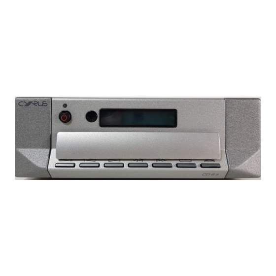
CYRUS CD6s FRONT PANEL PARTS DRAWING a b c 59 : 57 CD 6 s Front Panel parts Part Number Description AM-POWCP/ Standby knob trim AM-PLENS/ Power lens AM-LEMSM/02 Remote eye lens D3-DISPW/ Display window I6-FACIA/SB Cyrus CD6s front facia black... -
Page 22: Pcb Parts Lists
CYRUS CD6s PCB PARTS LIST CYRUS CD6s COMPONENT LIST RESISTORS R101 SMD0805 3.3k MF 1/8W 1% R102 SMD0805 3.3k MF 1/8W 1% R103 SMD0603 100R MF 1/16W 1% R104 SMD0603 100R MF 1/16W 1% R105 SMD0603 NOT FITTED R106 SMD0603... - Page 23 SMD0805 deleted R603 SMD0805 MF 1/8W 1% R604 SMD0805 NOT FITTED R605 AXIAL 0.6 MF 1/4W 5% R606 AXIAL 0.6 MF 1/4W 5% R607 SMD0805 MF 1/8W 1% © Cyrus Audio Ltd Nov 2006 Cyrus CD6s Service Manual Issue 2...
- Page 24 CYRUS CD6s PCB PARTS LIST R608 SMD0805 NOT FITTED R609 SMD0805 300R MF 1/8W 1% R610 SMD0805 300R MF 1/8W 1% R611 SMD0805 2.7k MF 1/8W 1% R612 SMD0805 2.7k MF 1/8W 1% R613 SMD0805 110R MF 1/8W 1% R614...
- Page 25 C413 CAPSMD6.3 NOT FITTED C419 SMD0603 NOT FITTED C420 SMD0603 NOT FITTED C421 CAPSMD5.0 NOT FITTED C422 CAPSMD5.0 NOT FITTED C423 CAPSMD5.0 NOT FITTED C424 CAPSMD5.0 NOT FITTED © Cyrus Audio Ltd Nov 2006 Cyrus CD6s Service Manual Issue 2...
- Page 26 CYRUS CD6s PCB PARTS LIST C425 SMD0603 NOT FITTED C426 SMD0603 NOT FITTED C427 CAPSMD6.3 NOT FITTED C428 CAPSMD6.3 NOT FITTED C429 SMD0603 NOT FITTED C430 SMD0805 NOT FITTED C431 SMD0805 NOT FITTED C432 SMD0805 NOT FITTED C433 SMD0805 NOT FITTED...
- Page 27 1A Rectifier Diode D508 SOT-23 BAW56 300mA Dual Signal Diode D601 NOT FITTED D602 1SR154-400 1A Rectifier Diode D603 1SR154-400 1A Rectifier Diode D604 DIODEBR2-SM DF02 1A Rectifier diode bridge © Cyrus Audio Ltd Nov 2006 Cyrus CD6s Service Manual Issue 2...
- Page 28 CYRUS CD6s PCB PARTS LIST D605 SOT-23 BZX84C11V 11V Zener Diode D606 deleted D607 DIODEBR2-SM DF02 1A Rectifier diode bridge D608 DIODEBR2-SM NOT FITTED TRANSISTORS T101 SOT-23 BC817-25 NPN Signal Transistor T102 SOT-23 BC817-25 NPN Signal Transistor T501 SOT-23 BC807-25...
- Page 29 NOT FITTED SK101 PHONOQUAD Quad Phono Gold plated, black sockets SK103 Black RCA NOT FITTED SK501 PHONODUAL Dual Phono Gold plated, black sockets OTHER PARTS TOTX101 TOX179 Optical output © Cyrus Audio Ltd Nov 2006 Cyrus CD6s Service Manual Issue 2...
-
Page 30: Circuit Diagrams
CYRUS CD6s CIRCUIT DIAGRAMS Circuit diagram index The Cyrus CD6s circuit diagrams are listed below. SHEET 1 ........Connectors and digital audio output SHEET 2 ........Clock generation SHEET 3 ........Left and Right channel DtoA converter SHEET 4 ........Microcontroller SHEET 5 ........ - Page 31 LEFT_OUT IC203C SPDIF +5VCD To Front Panel PCB T101 TOTX101 R101 74HC14 CLAMP IC203D +5VCC VADC R106 CON101 INPUT 12 Way LIF Side Entry 1.25mm Pit BC817 100R 0603 C113 74HC14 KEYS_IN1 IC203E TO MICRO DGND LED_RED LED_GRN C109 74HC14 SK101A +VBACKLIGHT H8/3644...
- Page 32 +5VCD C201 DGND +5VCD DATA: Left Justified IC201A C202 10n 0603 BCLK: 48fs I2S_WCLK DGND WCLK: L- /R XCLK: 384fs RP204 470n 0603 100k * 4 +5VCD +5VCD 74HCT86 DGND IC202 RP201 RP202 100R * 4 IC206A IC206B DAC_BCLK IC201D R217 R216 I2S_DATA...
- Page 33 OP amp decoupling Capacitors +15VAN IC302 Caps IC303 Caps IC304 Caps IC305 Caps +3V3_DAC_Left +5V_DACL C331 C333 C335 C337 100n 100n 100n 100n DAC_GND_AL DECGNDL1 DECGNDL1 DECGNDL3 DECGNDO DGND C330 C332 C334 C336 C321 C323 100n 100n 100n 100n C303 C305 22uF/16V 22uF/16V...
- Page 34 +5VCC C501 VADC +5VCC 22uF/16V +5VCC +5VCC C502 DGND 10n 0603 R507 R503 74HC14 74HC14 IC501A IC501F CD8/CD6 DGND IC501D MISO LCD_DATA R504 PHONODUAL R502 LCD_SCLK SK501 R508 74HC14 MC_BUS_IN MOSI MC_IN IC501B 74HC14 74HC14 DGND R509 IC501C IC501E MC_OUT MISO KEYS_IN1 74HC14...
- Page 35 HVA1 C608 LVA1 CON601 C602 100n HVA1 HVA2 10n 0603 C601 HVA1 100n R601 R603 1SR154-400 TIP31 C603 D602 100n T601 +9V_MOTOR LVA2 CONPOWER6 R605 HVA2 1R0 NFR HVA2 HVB2 HVB1 1SR154-400 R607 Axial 0.6 D603 C646 C664 2200uF/25V 4700uF/25V C611 T602 BC817...
Need help?
Do you have a question about the CD6s and is the answer not in the manual?
Questions and answers