
Related Manuals for Sy-G Challenger Series

Summary of Contents for Sy-G Challenger Series
-
Page 1: User Manual
USER MANUAL Online UPS: Challenger Series Rack Mount (RM) 220 VAC Capacity: 6 KVA ~ 10 KVA REVISION DESCRIPTION DATE Rev. 1.1 Formal Release 2016/01/27... - Page 2 Warning: Caution Unsafe practices that could endanger health, safety and cause financial damage. Important Any important technical and operating information on the equipment, should not neglected. Annotation Sy-G reserves the right to alter the features of its products without prior notice.
-
Page 3: Table Of Contents
CONTENTS 1. Safety Warning ............................2 1.1. Transportation ........................... 2 1.2. Preparation ............................2 1.3. Installation ............................2 1.4. Connection warnings ........................3 1.5. Operation ............................4 1.6. Standards…….……………………………………………………………...………………………………………..4 2. Installation and Setup ..........................5 2.1. Unpacking and Inspection ......................5 2.2. -
Page 4: Safety Warning
1. Safety Warning Please read carefully the following user manual and the safety instructions before installing the unit or using the unit! 1.1. Transportation Please transport the UPS system only in the original package to protect against shock and impact. The UPS must be stored in the room where it is ventilated and dry. -
Page 5: Connection Warnings
An integral single emergency switching device which prevents further supply to the load by the UPS in any mode of operation should be provided in the building wiring installation. Connect the earth before connecting to the building wiring terminal. Installation and Wiring must be performed in accordance with the local electrical laws and regulations. -
Page 6: Operation
BEFORE WORKIN ON THIS CIRCUIT Isolate Uninterruptible Power System (UPS). The check for Hazardous voltage between all terminals including the protective earth. RISK OF VOLTAGE BACKFEED. 1.5. Operation Do not disconnect the mains cable on the UPS system or the building wiring outlet (shockproof socket outlet) during operations since this would cancel the protective earthing of the UPS system and of all connected loads. -
Page 7: Installation And Setup
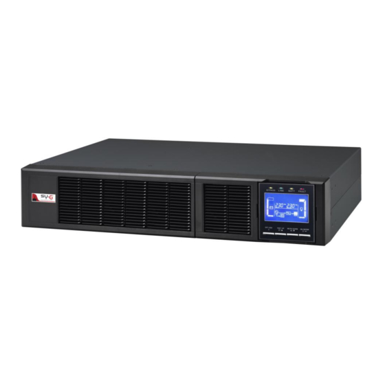
2. Installation and Setup Before installation, please inspect the unit. Be sure that nothing inside the package is damaged. Please keep the original package in a safe place for future use. Parallel function is also available for these two types and related installation and operation of Parallel function will be described in detail in the following content. - Page 8 Description UPS External battery connector. Input circuit breaker. RS-232 communication port. Input/Output terminals. Page | 6...
-
Page 9: Single Ups Installation
Maintenance bypass switch Intelligent slot. (option). USB communication port. Output terminal. Emergency power off function Ground. connector (EPO connector). Cooling fan. Input terminal. Battery pack output circuit breaker. 2.3. Single UPS Installation Installation and wiring must be performed in accordance with the local electric laws/regulations and execute the following instructions by professional personnel. - Page 10 5) Remove the terminal block cover on the rear panel of UPS. Then connect the wires according to the following terminal block diagrams: (Connect the earth wire first when making wire connection. Disconnect the earth wire last when making wire disconnection!) NOTE 1: Make sure that the wires are connected tightly with the terminals.
-
Page 11: Software Installation
pack and the UPS. But for other external battery pack, make sure a DC breaker or other protection device between UPS and external battery pack is installed. If not, please install it carefully. Switch off the battery breaker before installation. NOTE: Set the battery pack breaker in “OFF”... -
Page 12: Operations
3. Operations 3.1. Button Operation BUTTON FUNCTION o TURN ON the UPS: Press and hold the button more than 1s to turn on the UPS. ON/Enter Button o Enter Key: Press this button to confirm the selection in setting menu. o TURN OFF the UPS: Press and hold the button more than 1s to OFF/ESC Button turn off the UPS. -
Page 13: Lcd Panel
3.3. LCD Panel DISPLAY FUNCTION REMAINING BACKUP TIME INFORMATION Indicates the remaining backup time in pie chart. Indicates the remaining backup time in numbers. H: hours, M: minute, S: second FAULT INFORMATION Indicates that the warning and fault occurs. Indicates the warning and fault codes, and the codes are listed in details in 3-9 section. -
Page 14: Audible Alarm
Indicates the ECO mode is enabled. Indicates the Inverter circuit is working. Indicates the output is working. BATTERY INFORMATION Indicates the Battery level by 0-25%, 26-50%, 51-75%, and 76- 100%. Indicates the battery is fault. Indicates low battery level and low battery voltage. INPUT &... -
Page 15: Single Ups Operation
Bus unbalance Inverter soft start failure High Inverter voltage Beeping continuously Low Inverter voltage Inverter output short circuited Over temperature Overload 3.5. Single UPS Operation 3.5.1. Turn on the UPS with utility power supply (in AC mode) 1) After power supply is connected correctly, set the breaker of the battery pack at “ON”... -
Page 16: Connect Devices To Ups
3.5.3. Connect Devices to UPS After the UPS is turned on, you can connect devices to the UPS. 1) Switch on the devices one by one and it will display total load level in LCD panel. 2) If it is necessary to connect the inductive loads such as a printer, the in-rush current should be calculated carefully to see if it meets the capacity of the UPS, because the power consumption of this kind of loads is too big. -
Page 17: Turn Off The Ups (In Ac Mode)
2) In Battery mode, if buzzer sound annoys, users can press the Mute button to disable the buzzer. 3) The backup time of the long-run model depends on the external battery capacity. 4) The backup time may vary from different environment temperature and load type. -
Page 18: Operation In Fault Mode
1) When Fault LED flashes and the buzzer beeps once every second, it means that there are some problems for UPS operation. Users can get the warning code from LCD panel. Please check trouble shooting table in chapter 4 for details. 2) Some warning alarms can’t be muted unless the error is fixed. - Page 19 3.7. LCD Setting There are three parameters to set up the UPS. Parameter 1: It is for program alternatives or setting options. Refer to below table. Parameter 2 and Parameter 3: Are the setting options or values for each program. Programs available list for PARAMETER 1.
- Page 20 Charger maximum current setting Battery capacity and groups setting Backup time calibration Y means that this program can be set in this mode. 01: Output voltage setting. INTERFACE SETTING Parameter 3: Output voltage 208/220/230/240 VAC models, you may choose the following output voltage: 208: presents output voltage is 208Vac.
- Page 21 If 50 Hz selected in parameter 2, UPS will transfer to battery mode when input frequency is not within 46~54 Hz. If 60Hz selected in parameter 2, UPS will transfer to battery mode when input frequency is not within 56~64 If Parameter 2 is ATO, the Parameter 3 will show the current frequency.
- Page 22 06: Reserved. INTERFACE SETTING Reserved 07: Reserved. INTERFACE SETTING Reserved 08: Bypass mode setting. INTERFACE SETTING Parameter 2, please press “Enter” key first. Then, you have the following options: OP: Bypass allowed. When selected, UPS will run at Bypass mode depending on bypass enabled/disabled setting.
-
Page 23: Lcd Setting
09: Battery backup time setting. INTERFACE SETTING Parameter 3: 000~999: Set the maximum backup time from 0min to 999min. UPS will shut down to protect battery after backup time arrives. DIS: Disable battery discharge protection and backup time will depend on battery capacity. 10: Reserved. - Page 24 13: Battery voltage calibration. INTERFACE SETTING Parameter 2: Select “Add” or “Sub” function to calibrate battery voltage to real figure. Parameter 3: The voltage setting range is from 0V to 5.7V. (Default value is 0V). 14: Reserved. INTERFACE SETTING Reserved 15: Inverter voltage calibration.
- Page 25 17: Constant charger voltage adjustment. INTERFACE SETTING Parameter 2: You may choose “Add” or “Sub” to constant charger voltage. Parameter 3: The voltage setting range is from 0V to (Default value is 0V). 18: Maximum charger current setting. INTERFACE SETTING Parameter 3: The maximum charging current could be adjusted;...
-
Page 26: Operating Mode/Status Description
3.8. Operating Mode/Status Description This section describes the mode and operating status of the UPS, read carefully before making any configuration. Operating Mode/Status When the input voltage is within acceptable range, UPS will provide pure Description and stable AC power to output. The UPS will also charge the battery at AC mode. -
Page 27: Faults Reference Code
Bypass LCD display mode When UPS is in AC mode or CVCF mode, press “Test” key for more than 1s. Then the UPS will beep once and start “Battery Test”. The line Description between I/P and inverter icons will blink to remind users. This operation is used to check the battery status. -
Page 28: Warning Indicator
3.10. Warning Indicator WARNING ICON (FLASHING) ALARM Beeping every second Battery low Overload Beeping twice every second Beeping every second Battery unconnected Over charge Beeping every second EPO enable Beeping every second Over temperature Beeping every second Charger failure Beeping every second Overload 3 times in 30 min. -
Page 29: Troubleshooting
4. Troubleshooting If the UPS system does not operate correctly, solve the problem by using the table below: SYMPTOM POSSIBLE CAUSE REMEDY No indication and alarm in the The AC input power is not Check if input cable firmly front display panel even though connected well. - Page 30 Contact your dealer Battery backup time is shorter Batteries defect replace the battery. than nominal value The icon flash on The UPS temperature is Check fans notify LCD display and alarm beeps too high. dealer. every second. Page | 28...
-
Page 31: Storage And Maintenance
5. Storage and Maintenance Storage Before storing, charge the UPS at least 7 hours. Store the UPS covered and upright in a cool, dry location. During storage, recharge the battery in accordance with the following table: STORAGE TEMPERATURE RECHARGE FREQUENCY CHARGING DURATION -25°C - 40°C Every 3 months... - Page 32 When replace the batteries, install the same number and same type of batteries. Do not attempt to dispose of batteries by burning them. This could cause battery explosion. The batteries must be rightly deposed according to local regulation. Do not open or destroy batteries. Escaping electrolyte can cause injury to the skin and eyes.
-
Page 33: Technical Specifications
Derate to 80% of capacity in Frequency converter mode and to 80% when the output voltage is adjusted to 208 VAC SY-G reserves the right to change or modify product design, construction, specifications, or materials without prior notice and without incurring any obligation to make such changes and modifications on SY-G products previously or subsequently sold.
Need help?
Do you have a question about the Challenger Series and is the answer not in the manual?
Questions and answers