Advertisement
Quick Links
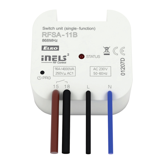
RFSA-11B, RFSA-61B
Wireless switch unit
EN
Indication, manual control
• LED STATUS - indication of the device status.
LED
button
• Manual control is performed by pressing the PROG
button for less than 1s.
• Programming is performed by pressing the PROG
button for more than 1s.
Delete actuator
Deleting one position of the transmitter
By pressing the programming button on the actuator for
5 seconds, deletion of one transmitter activates. The LED
fl ashes in an interval of 1s.
Pressing the required button on the transmitter deletes it from
the actuator's memory.
The LED goes out and the actuator returns to operating mode.
1 x
> 5s
PROG
Warning
Instruction manual is designated for mounting and also for user of the device. It is always a part of its packing. Installation and connection can be carried out only by a person with adequate professional qualifi cation upon understanding
this instruction manual and functions of the device, and while observing all valid regulations. Trouble-free function of the device also depends on transportation, storing and handling. In case you notice any sign of damage, deformation,
malfunction or missing part, do not install this device and return it to its seller. It is necessary to treat this product and its parts as electronic waste after its lifetime is terminated. Before starting installation, make sure that all wires, connected
parts or terminals are de-energized. While mounting and servicing observe safety regulations, norms, directives and professional, and export regulations for working with electrical devices. Do not touch parts of the device that are energized –
life threat. Due to transmissivity of RF signal, observe correct location of RF components in a building where the installation is taking place. RF Control is designated only for mounting in interiors. Devices are not designated for installation into
exteriors and humid spaces. The must not be installed into metal switchboards and into plastic switchboards with metal door – transmissivity of RF signal is then impossible. RF Control is not recommended for pulleys etc. – radiofrequency
signal can be shielded by an obstruction, interfered, battery of the transceiver can get fl at etc. and thus disable remote control.
Programming with RF control units
address
The address listed on the front of the actuator is
used for programming and controlling actuators by
RF control units.
Deleting the entire memory
By pressing the programming button on the actuator for
8 seconds, deletion occurs of the actuator's entire memory. The
LED fl ashes three times and goes out, then again fl ashes three
times and goes out.
The actuator goes into the programming mode, the LED fl ashes
in 0.5s intervals (max. 4min.).
You can return to the operating mode by pressing the Prog
button for less than 1s.
1 x
> 8s
PROG
RFSA-11B, RFSA-61B
Wireless switch unit
EN
Characteristics
• The switching unit with 1 output channel is used to control appliances, lights (easy to integrate it to
control garage doors or gates).
• It can be combined with Control or System units iNELS RF Control.
• The BOX design lets you mount it right in an installation box, a ceiling or controlled appliance cover.
• It enables connection of the switched load up to 16A (4.000 W).
• RFSA-11B: single-function design - switch on / off.
• RFSA-61B: multi-function design – button, impulse relay and time function of delayed ON or OFF
with time setting of 2s-60 min.
• The switching unit may be controlled by up to 32 channels (1 channel represents 1 button on the
controller).
• The programming button on the unit is also used for manual control of the output.
• Range up to 200 m (in open space), if the signal is insufficient between the controller and unit, use
the signal repeater RFRP-20.
• Communication frequency with bidirectional protocol iNELS RF Control.
Connection
RFSA-11B/230V
RFSA-11B/230V
RFSA-11B/24V
RFSA-11B/120V
RFSA-11B/120V
RFSA-61B/24V
RFSA-61B/230V
RFSA-61B/230V
RFSA-61B/120V
RFSA-61B/120V
L
L
N
N
12-24V AC/DC
Attention:
When you instal iNELS RF Control system, you have to keep minimal distance 1 cm between each units.
Between the individual commands must be an interval of at least 1s.
Assembly
mounting in an installation box
Radio frequency signal penetration through various construction materials
☺
☺
☺
☺
Tel: +31(0)228-567729, Fax: +31(0)228-567797, Email: info @ wardenaar.com, Internet: www.wardenaar.com
4/4
Technical parameters
Supply voltage:
230 V AC / 50-60 Hz
Apparent input:
7 VA / cos φ = 0.1
Dissipated power:
0.7 W
Supply voltage tolerance:
Output
Number of contacts:
Rated current:
Switching power:
Peak current:
Switching voltage:
Max. DC switching power:
Mechanical service life:
Electrical service life (AC1):
Control
RF, by command from transmitter:
Manual control:
L
Range in free space:
N
Other data
Operating temperature:
Operating position:
Mounting:
Protection:
Overvoltage category:
Contamination degree:
Terminals (CY wire, cross-section):
Length of terminals:
Dimensions:
Weight:
Related standards:
EN 60669, EN 300220, EN 301489 R&TTE Directive, Order. No 426/2000 Coll. (Directive 1999/EC)
mounting into the light cover
ceiling mounted
☺
60 - 90 %
80 - 95 %
20 - 60 %
wooden structures
reinforced
brick walls
with plaster boards
concrete
Perenmarkt 10B, 1681PG ZWAAGDIJK-OOST ind.terrein: WFO/ABC THE NETHERLANDS
Rabobank 32 69 98 268, KvK te Alkmaar 37079598, BTW NL 8070.48.768.B01
120 V AC / 60Hz
12-24 V AC/DC 50-60Hz
7 VA / cos φ = 0.1
-
-
0.7 W
0.7 W
+10 %; -15 %
1x switching (AgSnO
)
2
16 A / AC1
4000 VA / AC1, 384 W / DC
30 A / < 3 s
250 V AC1 / 24 V DC
500 mW
7
3x10
5
0.7x10
866 MHz, 868 MHz, 916 MHz, 922 MHz
button PROG (ON/OFF)
up to 200 m
-15 ... + 50 °C
any
free at lead-in wires
IP30
III.
2
2
2
2x 0.75 mm
, 2x 2.5 mm
90 mm
49 x 49 x 21 mm
46 g
0 - 10 %
80- 90 %
metal partitions
common glass
02-48/2015 Rev.3
1/4
Advertisement

Related Manuals for iNels RFSA-11B


Summary of Contents for iNels RFSA-11B
- Page 1 Attention: Weight: 46 g When you instal iNELS RF Control system, you have to keep minimal distance 1 cm between each units. Related standards: EN 60669, EN 300220, EN 301489 R&TTE Directive, Order. No 426/2000 Coll. (Directive 1999/EC) Between the individual commands must be an interval of at least 1s.
- Page 2 LED is fl ashing in 1 s between individual (LED switches off ). 11B for 1 second will transmitter assigns the RFSA-11B shorter then 1s interval. presses). activate actuator RFSA- function "close". The 1 second will fi nish The output contact >...