
Related Manuals for Vislink HDX-1100


Summary of Contents for Vislink HDX-1100
- Page 1 HDX-1100 Aircraft/Terrestrial High Power SD/HD Video Transmitter User and Technical Manual Manual Part No. 400609-1 Rev. A - Sept 2011...
- Page 2 The foregoing does not apply to vendor proprietary parts. Vislink has made every effort to ensure the accuracy of the material contained in this manual at the time of printing. As specifications, equipment, and this manual are subject to change without notice, Vislink assumes no responsibility or liability whatsoever for any errors or inaccuracies that may appear in this manual or for any decisions based on its use.
- Page 3 C2 Band 4.4 - 5.0 GHz C3 Band 6.4 - 7.1 GHz The HDX-1100 may be operated via the touch screen user interface (see Section 4), however it is typically controlled by an optional aircraft remote panel (RCU) (see Section 5).
-
Page 4: Operating In Safety
RF power may be present. The HDX-1100, operated without an antenna will not create RF energy exceeding 1.0 mW/cm the FCC limit for exposure. Connecting an antenna to the unit greatly enhances the potential for harmful exposure, and you must maintain a certain distance from the radiator. - Page 5 FCC OET Bulletin 65, August 1997 - Evaluating Compliance with FCC Guidelines for Human Exposure to Radio Frequency Electromagnetic Fields The figure below is a typical graph for a Vislink HDX-1100 Transmitter and shows the permissible exposure distance for various antenna gains. Graphs and data will vary, based on the actual transmitter, output power, frequency, and antenna utilized.
-
Page 6: Touch Screen Display
Installing an HDX-1100 Transmitter The HDX-1100 is built in an ARINC compliant 3/8 ATR housing, and was designed primarily for aircraft operation. It is also suitable for general mobile applications, including terrestrial vehicles. The transmitter and its remote control panel (RCU) have been tested and certified to be compliant with RTCA DO-160F, as recognized by the FAA and other global agencies that regulate aircraft operation and safety. - Page 7 WEB BROWSER MANAGEMENT (Ethernet) DC CIRCUIT BREAKER RF OUTPUT HDX-1100 REAR PANEL The following electrical connections will be found on the rear panel of the HDX-1100. Video Inputs and connector types: Video 1: BNC female – NTSC or PAL composite Video 2 - BNC female –...
- Page 8 NOTE: There is a 10 AMP DC circuit breaker on rear panel of HDX-1100. If the power to this breaker is fed from another circuit breaker in the aircraft, the HDX-1100 breaker should be left in the on position. To operate the breaker: push in = ON, pull out = OFF, a manual reset is required after the breaker trips.
- Page 9 The spacers would not be needed if the mounting plate is attached to a shelf within the airframe, as shown below. HDX-1100 in optional 3/8 ATR tray installed on existing shelf without spacers...
- Page 10 4. The new CHANNEL selection will remain so until it is changed. Selecting the RF Output Level The HDX-1100 recalls the most recently saved RF output power level when it is powered up. To select between high or low power for the RF output level, do the following: 1.
- Page 11 Setting the HDX-1100 with the Aircraft Remote Panel You can install the Aircraft remote control unit (RCU) up to 50 feet from the HDX-1100 using a 3-wire serial interconnection and a power source. The following figure shows the RCU. Remote Control Unit – Part Number 907621-6 NOTE: Both the HDX-1100 touch screen and the RCU remote panel are active and capable of control when the RCU is powered on.
- Page 12 Use a 9-pin RS-232 null-modem cable to connect the communication path between the RCU and the HDX-1100. A receptacle at the rear of the controller supplies DC power to the RCU. Vislink provides the 2-pin Weidmuller connector (Part # 52104-2) to connect to the power receptacle at the rear of the controller.
- Page 13 HDX-1100. 2. Open a web browser on your PC and type 192.168.1.150 into the URL address field and press Enter. The screen will change to the HDX-1100 log-in page, as shown below. The factory defaults are: User Name = admin...
-
Page 14: Main Screen
6.1 MAIN SCREEN: After the login procedure is complete, the browser will open to the MAIN SCREEN, providing a view of operating conditions for the currently active pre-set. A drop down menu on the pre-set line allows you to change to any available pre-set and review the parameters for each pre-set. Changes to pre-sets CANNOT be made from this screen of the browser. -
Page 15: Setup Screen
I n t h e s c r e e n s h o t b e l o w , ― R a d i o ‖ h a s b e e n s e l e c t e d f r o m t h e d r o p d o w m e n u b a r o n t h e t o p , a n d ―... - Page 16 I n i t i a l S e t u p : C l i c k o n t h e w o r d ― S e t u p ‖ i n m e n u b a r a t t h e t o p o f t h d i s p l a y .
- Page 17 w h i l e t h e R E S E T b u t t o n w i l l c a n c e l a n y p r o g r a m m i n g a c t i o n c u r r e n t l y...
- Page 18 e n t e r e d , b u t n o t y e t s u b m i t t e d . C l i c k i n g t h e R E S E T w i l l r e t u r n y o u t o t h e p r e v i o u s s c r e e n .
- Page 19 6 . 3 R a d i o N e t w o r k S c r e e n : T h e v a l u e s i n i t i a l l y f o u n d i n t h e I P a d d r e s s , S u b n e t , a n d G a t e w a y d i a l o g b o x e s o f t h e r a d i o n e t w o r k s c r e e n a r e f a c t o r y d e f a u l t s .
- Page 20 6 . 4 C O N F I G U R I N G P R E S E T S F o r m a x i m u m f l e x i b i l i t y , a c o m p l e t e s e t o f p a r a m e t e r s m u s t b e d e f i n e d f o r e a c h p r e s e t t h a t i s p r o g r a m m e d i n t o t h e H D X - 1 1 0 0 .
- Page 21 M O D U L A T I O N S E T U P S C R E E N M o d u l a t i o n s e t u p d e t e r m i n e s t h e b i t r a t e t h a t t h e t r a n s m i t t e r c a n s e n d t o t h e r e c e i v i n g s t a t i o n f o r e a c h p r e s e t .
- Page 22 Available bitrates (Mbit/s) for a DVB‐T system in 6 MHz channels Guard interval Modulation Coding rate 1/16 1/32 3.732 4.147 4.391 4.524 4.976 5.529 5.855 6.032 QPSK 5.599 6.221 6.587 6.786 6.221 6.912 7.318 7.540 6.532 7.257 7.684 7.917 7.465 8.294 8.782 9.048 9.932 11.059 11.709 12.064 16‐QAM 11.197 12.441 13.173 13.572 12.441...
- Page 23 Two dialogue boxes will appear: Video In, and, Encryption. See next graphic for details. IMPORTANT: When equipped with the MPEG-2 encoding option, HDX-1100 presets may be programmed all in MPEG-2 mode, all in H.264/MPEG-4 mode, or as a mix of the two.
- Page 24 Video and Encryption Mode set-up Screen If encryption is to be used, select Encryption from the Video drop down menu, and configure the encryption mode and key as required for encrypted preset, and click Submit. Note: For 128-bit encryption, enter 32 hexadecimal characters. For 256-bit encryption, enter 64 hexadecimal characters.
- Page 25 6 . 6 C H A N N E L S E T U P Normally, a customer specified channel plan is set up at the factory when the HDX-1100 is built, however, additional channels may be added at any time, or existing channels may be redefined if necessary.
- Page 26 Once this procedure has been completed, the pre-sets that were established may be recalled using the aircraft remote panel. NOTE: The HDX-1100 transmit frequency settings may be configured via the web browser, or from the HDX-1100 front panel. See section 7 for details.
-
Page 27: Main Screen Operation
MAIN SCREEN OPERATION When operating the HDX-1100 transmitter in local mode (touch screen active), the main screen will be displayed first. The current preset and channel selections are controlled by touching the up and down buttons below the respective sections of the display. For example, to move to a lower channel, touch the down arrow below the CHANNEL bar in the main screen. - Page 28 7.1 SETTING OR MODIFYING CHANNEL FREQUENCY To initiate or modify a channel frequency, first select the channel assignment to be modified on the main screen, then touch the CHANNEL MENU button on the main screen; the display will change to the screen shown above. To access the channel assignment menu, first touch the SET FREQUENCY button on the screen.
-
Page 29: Video Input Connectors
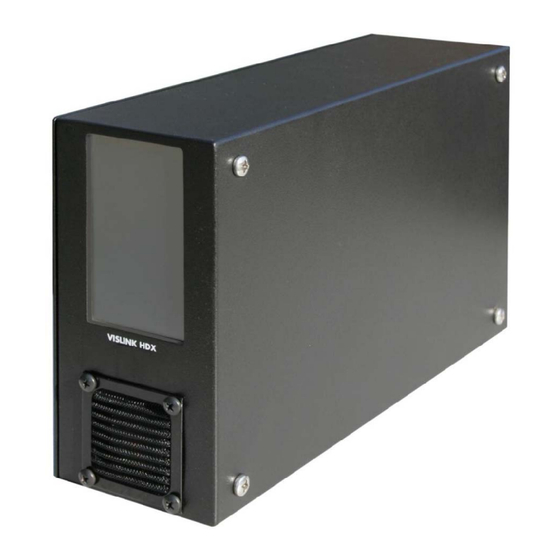
8.0 HDX-1100 Specifications The following figure shows the front, back, top, and side views of the HDX-1100. • Dimensions: 3.65 x 7.62 x 12.68 inches (ARINC ATR 3/8 compliant size) • Weight: 8 pounds (3.6 kg) • Operating temperature: – 10 °C to +55 °C; storage temperature: – 40 °C to +75 °C •... - Page 30 DC POWER and CONTROL Connector DC voltage for the HDX-1100 is +10 Vdc to +32 Vdc with reverse voltage protection. Ensure that the power being supplied matches the power required by the equipment. I/O connector pin-outs are shown in the following table:...
-
Page 31: Rf Output Power
Encryption Only one type of encryption can be installed in each transmitter, and it must be done at the factory. The choices are limited to: • RCBC (Reverse Chain Block Ciphering) • AES 128-bit • AES 256-bit • BISS (available in MPEG-2 option only) Note ASI input streams are not encrypted 8.7 RF Output Power... - Page 32 SMPTE 292M as defined in SMPTE 349M. Local System Access and Management Interfaces The front panel of the HDX-1100 includes an LCD touch screen that allows radio operating parameters to be initially configured and later modified by maintenance personnel. The...
- Page 33 • Model number and serial number of the unit (located on a label on the bottom of each unit). • Approximate purchase date. There are no supported field repairs to the HDX-1100. Return the unit for factory repair. CAUTION If you attempt field repair, you risk damaging your equipment. If your equipment is under warranty, you may also affect your warranty coverage.
-
Page 34: Glossary Of Terms
11.0 Glossary of Terms ARINC Aeronautical Radio, Inc. Maintains standards for line-replaceable units in a aviation, defense, government, healthcare and other industries. Asynchronous Serial Interface. B-Frame Contains difference information from the preceding and following I- or P- frame within a GOP COFDM Coded Orthogonal Frequency Division Multiplexing DVB-T... - Page 35 Appendix 1 The table and chart below summarizes the FCC channel plan for the 6.5 GHz band, as specified in part 101 of the commission’ s rules and regulations. Please note the restrictions on modulation bandwidth for the 8 MHz channels, as well as use of offsets within the 25 MHz channels. For US domestic applications, this is the default channel plan that is loaded into an HDX 1000 prior to shipment.
Need help?
Do you have a question about the HDX-1100 and is the answer not in the manual?
Questions and answers