Table of Contents
Advertisement
Quick Links
AP-3
Wireless Access
Control Receiver
Installation Instructions
(760) 438-7000 • FAX (760) 438-7043
USA & Canada (800) 421-1587 & (800) 392-0123
Toll Free FAX (800) 468-1340
www.linearcorp.com
SAFETY WARNINGS
MOVING DOOR OR GATE CAN CAUSE SERIOUS INJURY OR DEATH
STAY CLEAR OF MOVING PARTS IF UNIT IS MOUNTED
INSIDE DOOR OR GATE OPERATOR!
LEARNING OR DELETING TRANSMITTERS IN THIS UNIT
MAY CAUSE OPERATION OF DOOR/GATE MOTOR. STAY
CLEAR OF DOOR/GATE OR DISCONNECT RELAY WIRES
WHEN LEARNING OR DELETING TRANSMITTERS.
ELECTRICAL CONNECTIONS
EARTH GROUND
Ground stake, cold
water pipe or unified
earth ground.
EARTH GND
OPEN REQUEST
N.C.
ACCESS
K1
COM
RELAY
N.O.
N.C
OBSTACLE
K2
COM
RELAY
N.O
AC2
AC1
ACCESS AND OBSTACLE
RELAY TERMINALS
Connect to access device. Select
normally open or normally closed
POWER INPUT
terminals to match access device.
Low voltage plug-in
transformer or power
from access device.
The AP-3 is designed for a broad range of access control applications. Its wireless design
and small size make it easily adaptable for a variety of access control requirements.
Typically, the AP-3 is used to control a door strike, barrier gate, automatic gate or
automatic door operator.
The AP-3 contains a high-gain UHF receiver which uses an external antenna to pick up
signals from up to 250 feet away. Up to 339 Linear MegaCode® Format transmitters and
one Model MGT safety edge transmitter can easily be programmed into the AP-3's
memory. The AP-3 will retain its memory, even without power.
Two dry contact relay outputs are standard. One relay is the ACCESS RELAY, which
triggers for two seconds each time a programmed transmitter is activated. This relay
output connects to the pushbutton or radio input of the access device. The second relay
is the OBSTACLE RELAY, which triggers for two seconds when an obstacle signal is
sent from a Model MGT safety edge transmitter. This relay output connects to the obstacle
input of the access device. An OPEN REQUEST input terminal is supplied for hardwire
activation of the access device with an external pushbutton or keyswitch.
The AP-3 can be powered from 12-24 Volts AC or DC. The Form C relay outputs can
switch up to 1 Amp each. An EARTH GROUND terminal is provided as an optional
connection for maximum lightning and static protection.
Five special utility functions can be displayed by pressing the pound (#) key then the
LEARN BUTTON
Push after entering transmitter
number to start learn cycle. To
complete the cycle, activate a
transmitter while occupied light is
blinking.
DELETE BUTTON
Push once after entering the
transmitter number to delete.
Press again while the occupied
light is blinking to delete selected
transmitter from memory.
OPEN BUTTON
Push to activate the access
relay. Also clears any
supervisory trouble codes from
MGT transmitter.
LOCAL ANTENNA
Attach local whip
antenna directly to
receiver. Bend whip
to point antenna up.
OPEN REQUEST PUSHBUTTON
Optional connection provides
an external method to activate
access device.
Pushbutton
or Radio
Terminals
ACCESS DEVICE
Obstacle
Terminals
DC -
12-24
VOLTS
AC/DC
DC +
INTRODUCTION
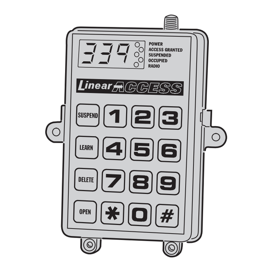
NUMERIC KEYPAD
DIGITAL DISPLAY
For entering memory
Displays transmitter numbers
location numbers and
during operation and programming.
utility function numbers.
Also displays MGT supervision
status and system utility information.
SUSPEND BUTTON
Prevents selected transmitter from
activating the access relay but
does not remove it from memory.
STAR ( ) KEY
Displays the number of the last
transmitter activated or
subtracts 1 from the displayed
number.
ANTENNA INSTALLATION
REMOTE ANTENNA
REMOTE ANTENNA
Use the optional EXA-1000
Mount F-81 connector
or EXA-2000 antenna
on surface using
mounted as high as
lockwasher and nut.
possible for best radio
Connect to receiver
range. Connect to
with coax cable and
receiver with RG-59
screw whip antenna to
coax cable.
connector.
ATTACH
WHIP
ANTENNA
EXA-1000
ANTENNA
EXA-2000
DIRECTIONAL
ANTENNA
F-81
CONNECTOR
COAX TO
RECEIVER
digits 1-5. The utility functions display the status of the obstacle transmitter, the number
of empty programming locations, the total number of transmitters programmed, first
available programming location and firmware version number.
The AP-3 can fully supervise the MGT safety edge transmitter. The system monitors the
MGT transmitter for hourly status reports, tamper signals and low battery signals. A beep
will sound every 5 seconds if a fault occurs and the trouble source can be displayed by
pressing pound (#)-1. For a trouble indication, a transmitter must be activated twice to
trigger the ACCESS RELAY if a supervisory condition exists on the MGT transmitter.
WHIP
ANTENNA
MODEL AP-3 RECEIVER
AP-3 FEATURES
ANTENNA CONNECTOR
For direct connection to the local
whip antenna or, with coax cable, to
the remote antenna.
ACCESS GRANTED INDICATOR
Lights when the access
or obstacle relay is
energized.
POUND (#) KEY
Adds 1 to the displayed number. Also
press # then 1-5 for utility functions:
#-1 Displays MGT supervisory status.
#-2 Displays number of empty memory locations.
#-3 Displays number of occupied memory locations.
#-4 Displays first available memory location.
#-5 Displays firmware version number.
RECEIVER INSTALLATION
MOUNT RECEIVER
USING THE TWO
SCREWS PROVIDED
SECURE CASE CLOSED USING
THE TWO SCREWS PROVIDED
MOUNTING
SCREWS
CASE
SCREWS
F-81 CONNECTOR
3-FOOT
NUT AND
ANTENNA
LOCKWASHER
CABLE
POWER INDICATOR
Lights when AC or DC
power is applied to the
unit.
SUSPENDED INDICATOR
Lights when a signal is received
from a transmitter that has been
suspended from use.
OCCUPIED INDICATOR
Lights when the displayed
memory location is occupied.
Blinks during transmitter learn
cycle and before transmitter
is deleted.
RADIO INDICATOR
Lights when a radio
signal is detected on the
frequency to which the
receiver is tuned.
1. Mount receiver in an area
protected from the elements.
2. If using the local whip
antenna, the higher the
receiver is mounted, the
better the radio range will be.
3. Optionally, mount the
receiver in a metal cabinet
and use an external antenna.
Advertisement
Table of Contents

Related Manuals for Linear AP-3


Summary of Contents for Linear AP-3
- Page 1 WHIP ANTENNA The AP-3 can be powered from 12-24 Volts AC or DC. The Form C relay outputs can switch up to 1 Amp each. An EARTH GROUND terminal is provided as an optional (760) 438-7000 • FAX (760) 438-7043 F-81 CONNECTOR connection for maximum lightning and static protection.
- Page 2 Operating Temperature Range: -22° to +158° F (-30° to +70° C) as labeled on the product. This Linear Corporation Warranty is in lieu of all other warranties express or implied. For warranty service on Linear equipment return product, at sender’s expense to:...
Need help?
Do you have a question about the AP-3 and is the answer not in the manual?
Questions and answers