Table of Contents
Advertisement
™
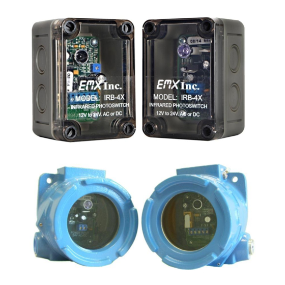
IRB-4X
INCLUDES MODEL I RB-EXP
T H R U B E A M P H O T O E Y E
U L 3 2 5 N O N - C O M P L I A N T
IRB-EXP (for explosive environments)
4564 Johnston Parkway, Cleveland, Ohio 44128
P. 800 426 9912 F. 216 518 9884
Sales Inquiries: salessupport@emxinc.com
Technical Support: technical@emxinc.com
www.emxinc.com
Advertisement
Table of Contents

Related Manuals for EMX IRB-4X


Summary of Contents for EMX IRB-4X
- Page 1 ™ IRB-4X INCLUDES MODEL I RB-EXP T H R U B E A M P H O T O E Y E U L 3 2 5 N O N - C O M P L I A N T...
-
Page 2: Table Of Contents
Contents Cautions and Warnings Product Overview Specifications Controls and Indicators Connections Operational Settings Troubleshooting Installation Ordering Information Accessories Warranty IRB-4X™ Operating Instructions Document no. 10060104... -
Page 3: Cautions And Warnings
UL 325 Non-compliant Product Overview The IRB-4X is used as a safety, reversing, or opening device when used in conjunction with automatic operators, garage doors, rolling doors and parking barriers. Its generous 24 sensing angle makes this reliable photoeye easy to align. -
Page 4: Specifications
IRB-EXP: NEMA 4 & 7, NEC Class 1, Groups B, C, & D, Environmental Class II, Groups E, F, & G CSA certified, CENELEC certified, EExd IIC IRB-4X: 3.7” x 2.56” x 2.24” Size IRB-EXP: 4.69” x 4.5” x 3.44” Detection Angle... -
Page 5: Controls And Indicators
Transmitter Receiver Continuously adjustable single Green LED Power Indicator turn potentiometer figure 2 Sensitivity (1)IRB-4X-T has a 0 – 15 second Receiver relay timer to extend the relay output time figure 2 Green LED Power Indicator Red LED Detection Indication... -
Page 6: Operational Settings
Power LED Power LED Figure 1 Figure 2 IRB-4X Transmitter connections (figure 1) Sensitivity Gain Adjustment 1. Connect power (12 – 24V AC/DC) to Power input terminals (no polarity) LED2 Power LED will glow green when powered. -
Page 7: Troubleshooting
Chattering 1. Interference See step 7 under Operational settings and see if any reflective surfaces could be sending a signal into the receiver sensor IRB-4X™ Operating Instructions Document no. 10060104... -
Page 8: Installation
2. Remove grey front cover by removing (4) plastic retaining screws 3. Drill (4) mounting holes in surface of IRB-4X mounting location. 4. Place gold Aluminum hood or Powder coat Steel hood around IRB-4X unit to be mounted, place mounting screws through IRB-4X box and hood and attach to surface. -
Page 9: Ordering Information
Set of 2 Nylon screws with nuts IRB-EXP IRB Transmitter and Receiver in Explosive environment housing This manual covers the IRB-4X and IRB-EXP models. OBSOLETE PRODUCTS IRB-4X-T IRB Transmitter and Receiver in NEMA 4 enclosure with delay timer IRB-4X-T, IRB-4XW-T, IRB-4XW-T5... -
Page 10: Warranty
EMX Industries option of a part or parts found not conforming to the warranty. In no event shall EMX Industries Inc. be liable for damages, including but not limited to damages resulting from non-conformity, defect in material or workmanship. - Page 11 BLANK PAGE IRB-4X™ Operating Instructions Document no. 10060104...
- Page 12 4564 Johnston Parkway Cleveland, Ohio 44128 United States of America www.emxinc.com Technical Support: (216) 834-0761 technical@emxinc.com Sales: (216) 518-9888 Fax: (216) 518-9884 salessupport@emxinc.com Revision 1.7 2.28.18 IRB-4X™ Operating Instructions Document no. 10060104...
Need help?
Do you have a question about the IRB-4X and is the answer not in the manual?
Questions and answers