
Related Manuals for LEYBOLD Turbo.Drive TD20 classic


Summary of Contents for LEYBOLD Turbo.Drive TD20 classic
- Page 1 Turbo.Drive TD20 classic Frequency Converter for Turbomolecular Pumps Operating Instructions GA05228_002_C0 Part Nos. 800075V0001 to 800075V0008...
-
Page 2: Table Of Contents
Specific parameter data for the pumps 3.2.10 Error messages Start-up of the TURBOVAC Operation 3.4.1 Status table at default settings Shut-down of the TURBOVAC Shut-down of the Turbo.Drive TD20 classic Maintenance Troubleshooting EC Conformance Declaration Certificates GA05228_002_C0 - 11/2016 - © Leybold... -
Page 3: Important Safety Information
Warning Only qualified personnel or the Leybold Service Department may carry out work on the frequency converter. Potentially fatal voltages are present inside the frequency converter. Open the frequency converter only after it has been isolated from the mains power supply. -
Page 4: Description
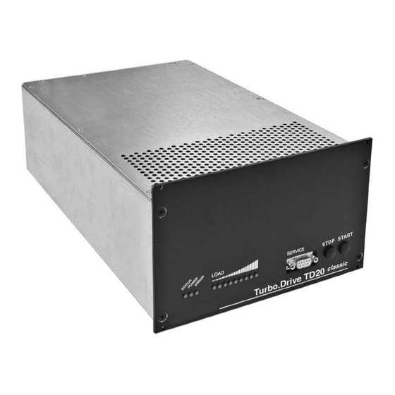
It can be connected directly to mains voltage. The Turbo.Drive TD20 can be connected directly to mains voltage. classic Supplied equipment Turbo.Drive TD20 table-top electronic frequency converter with housing, classic Operating Instructions. GA05228_002_C0 - 11/2016 - © Leybold... - Page 5 SERVICE interface RS 232 interface Key START Starting the TURBOVAC’s run-up Key STOP Switching the TURBOVAC off Resetting a failure report Fig. 1.1 Front panel of the Turbo.Drive TD20 classic GA05228_002_C0 - 11/2016 - © Leybold...
-
Page 6: Technical Data
5 to 85 % (non-condensing) Type of protection to EN 6059 IP 20 Electrical safety to EN 61010-1 Interference radiation to 61326-1 Class A EMC to IEC 801-2 Severity 2 Dimensions 1/2 19“, 3HU Weight 4 kg GA05228_002_C0 - 11/2016 - © Leybold... -
Page 7: Ordering Information
Integration of customer’s software n Record parameter data 800110V0102 (Software supports only RS 232, RS 485 and Profibus) The software can also be downloaded from www.leybold.com in the menu Documentation → Download Software GA05228_002_C0 - 11/2016 - © Leybold... -
Page 8: Installation
Installation Installation Warning Only qualified personnel or the Leybold Service Department may carry out work on the frequency converter. Potentially fatal voltages are present inside the frequency converter. Open the frequency converter only after it has been isolated from the mains power supply. -
Page 9: Providing The Connections
Insert and fasten the connection line to the motor of the TURBOVAC. Connect the interface, see Section 3.2. Warning Connect the instrument using the ground bolt to the protective ground system. Connect the power line cord. GA05228_002_C0 - 11/2016 - © Leybold... -
Page 10: Replacing The Nt
Phoenix contact strips, we are offe- ring for this purpose an adapter, see Section 1.5 and Fig. 2.3. The pin assignments of both interfaces are detailed in Section 3.2.1 and 3.2.5. GA05228_002_C0 - 11/2016 - © Leybold... - Page 11 23 Acceleration (Relay) (n.o.) Run-up (Relay) (n.o.) 24 Speed (Analog input) not connected (not implemented) Housing Connected with Cable shielding Housing ground (PE) Pins 7 and 8 Heating not connected Fig. 2.3 NT 20 adapter GA05228_002_C0 - 11/2016 - © Leybold...
- Page 12 TURBOVAC Turbo.Drive TD20 classic DRIVE POWER REMOTE Adapter cable Power line cord Old interface cable for the TURBOTRONIK NT 20 Fig. 2.5 Connections for the Turbo.Drive TD20 , with adapter cable, schematic representation classic GA05228_002_C0 - 11/2016 - © Leybold...
-
Page 13: Replacing The Nt 151/361 Or Nt 361
If you want to use the old connection cable you need the adapter cable 800 000 006. Alternatively you may use the Turbo.Drive TD20 version for pump con- classic nection with DIN plug (compatible with the NT 361 pump connector). GA05228_002_C0 - 11/2016 - © Leybold... -
Page 14: Operation
Note Upon delivery, the Turbo.Drive TD20 has been preset to the classic TURBOVAC 1100 so the special acknowledgement process will have to be run when commissioning any other pump for the first time. GA05228_002_C0 - 11/2016 - © Leybold... -
Page 15: Interfaces
The PC software „TURBO.DRIVE Server“ allows convenient access by the user to the parameters of the frequency converter. For further information on the interfaces refer to the Operating Instructions which are included with the respective device. GA05228_002_C0 - 11/2016 - © Leybold... -
Page 16: 9-Way Plc Interface
When switching on the Turbo.Drive TD20 the status at X1 will be uti- classic lized. The other (optional) interfaces behave differently. When controlling the instru- ment through them, the keys are disabled (except from the start-up). GA05228_002_C0 - 11/2016 - © Leybold... -
Page 17: Rs 232 Interface
For further information please refer to the Operating Instructions 17200048. Fig. 3.3 Pin assignment for the socket at the frequency converter (female) TURBO.DRIVE Shield 9-pin IBM PC RS 232 interface Fig. 3.4 Providing a RS 232 connection GA05228_002_C0 - 11/2016 - © Leybold... -
Page 18: Profibus Interface
For further information please refer to the Operating Instructions 17200048. Links for activation of the bus terminator 0,5 A, 24 V DC TxD/RxD + TxD/RxD – Fig. 3.5 Pin assignment for the socket at the frequency converter for RS 485 interface (male) GA05228_002_C0 - 11/2016 - © Leybold... - Page 19 TxD/RxD – 150 Ω 120 Ω TxD/RxD + 390 Ω TURBO.DRIVE X5 (7) X5 (8) X5 (7) X5 (8) TURBO. TURBO. Master DRIVE DRIVE Fig. 3.6 Connection of the RS 485 bus GA05228_002_C0 - 11/2016 - © Leybold...
-
Page 20: 25-Way Plc Interface
Connected to frame ground (PE) PLC = Programmable logic controller [H] = PLC high level > 11 V [L] = PLC low level < 8 V Input resistance 5…6kΩ External voltage resistance ± 40VDC The reserved pins must not be used. GA05228_002_C0 - 11/2016 - © Leybold... - Page 21 Supplies a start signal for the connected fan, if Parameter 318 has been set to 3. Upon delivery: The relay picks up as soon as normal operation is attained (motor 18 Fan n.o. current ≤ normal current threshold). 19 Fan com. 20 Fan n.c. Contact rating: 2A / 50V DC max. (resistive load) GA05228_002_C0 - 11/2016 - © Leybold...
-
Page 22: Devicenet Interface
* Set parameter 318 to 3 Fig. 3.7 Example for external connections compatible with the NT 20 (principle) 3.2.6 DeviceNet interface See additional Operating Instructions 17200055. 3.2.7 Ethernet/IP interface See additional Operating Instructions 17200056. GA05228_002_C0 - 11/2016 - © Leybold... -
Page 23: Parameter List
Defines from which frequency onwards normal operation threshold there is normal operation for the pump. Relay definition 0.1 A If P29 = 1 or 4: Defines from which motor normal current current onwards there is the normal operation. GA05228_002_C0 - 11/2016 - © Leybold... - Page 24 1 = Compatible with T1600 0 = Compatible with MagDrive Actual temperature pump housing °C Measured pump housing temperature. Warning temperature When the temperature warning threshold is pump housing P132 °C exceeded, the warning message is output. GA05228_002_C0 - 11/2016 - © Leybold...
- Page 25 Value 0.0: Indefinite time delay. In this way a change of the control right is inhibited. Values 0.1 ..6553.5: A change in the control right corresponding to the setting of parameter 179 is only effected after the time span defined through parameter 182 has elapsed. GA05228_002_C0 - 11/2016 - © Leybold...
- Page 26 Frequency at which the venting valve shall “vent off” frequency be switched off in case of a mains power failure. Power failure venting can be enabled through P240. RS 485 address R/W u16 Currently valid address at the bus adapter. GA05228_002_C0 - 11/2016 - © Leybold...
-
Page 27: Specific Parameter Data For The Pumps
Critical Maximum Pump housing Pump housing pump designation and setpoint frequency run-up time warning shutdown TURBOVAC frequency threshold temperature temperature P18, P24 P128 P132 1100 (C) 1000 (C) 600 (C) 361 (C) 151 (C) GA05228_002_C0 - 11/2016 - © Leybold... -
Page 28: Error Messages
* Error modes 0 and 1 are compatible with TD 1600 and MAG.DRIVE. ** Error mode 2 is the default setting for the TD20 classic The error mode can be set in Parameter 90. GA05228_002_C0 - 11/2016 - © Leybold... -
Page 29: Start-Up Of The Turbovac
Error has just occurred Start passive active Error is present; pump is at standstill or decelerating Start passive active flashes Error is present; pump is decelerating Start passive active flashes Error has just occurred GA05228_002_C0 - 11/2016 - © Leybold... -
Page 30: Shut-Down Of The Turbovac
We recommend adhering to a cleaning interval of about three years. Warning Only qualified personnel or the Leybold Service Department may carry out work on the frequency converter. Potentially fatal voltages are present inside the frequency converter. -
Page 31: Troubleshooting
After you have eliminated the cause of the failure, you can reset the malfunc- tion signal with the STOP command (key or remote control). Only qualified personnel or the Leybold Service Department may carry out Warning work on the frequency converter. - Page 32 LED 9 is not used. Two of the LEDs 1 to 5 flash, TURBO.DRIVE has Pump or frequency converter were changed. Run special acknowledgement, see Chapter detected a different pump. Installation. GA05228_002_C0 - 11/2016 - © Leybold...
-
Page 33: Ec Conformance Declaration
GA05228_002_C0 - 11/2016 - © Leybold... -
Page 34: Certificates
The Part Nos. 800075V0001 to 800075V0007 have been checked. The other frequency converters have not yet been tested by the TÜV, they are designed and tested following the same regulations. Certificate No. 72063165 01 GA05228_002_C0 - 11/2016 - © Leybold... -
Page 35: Ga05228_002_C0 - 11/2016 - © Leybold
GA05228_002_C0 - 11/2016 - © Leybold... - Page 36 Sales and Service Germany Great Britain America Leybold Japan Co., Ltd. Tsukuba Technical Service Center Leybold UK LTD. 1959, Kami-yokoba Leybold GmbH Tsukuba-shi, Ibaraki-shi 305-0854 Unit 9 Sales, Service, Support Center (3SC) Japan Silverglade Business Park Bonner Strasse 498 Leybold USA Inc.
Need help?
Do you have a question about the Turbo.Drive TD20 classic and is the answer not in the manual?
Questions and answers