Table of Contents
Advertisement
Available languages
Available languages
Advertisement
Chapters
Table of Contents

Related Manuals for LEYBOLD TURBOTRONIK NT 20


Summary of Contents for LEYBOLD TURBOTRONIK NT 20
- Page 1 Applikations- LEYBOLD VACUUM Vakuum-Lösungen Unterstützung Service GA 05.208/12 TURBOTRONIK NT 20 Elektronischer Frequenzwandler Electronic Frequency Converter Kat.-Nr. / Cat. No. 857 20/21/22 Gebrauchsanleitung Operating Instructions...
-
Page 2: Table Of Contents
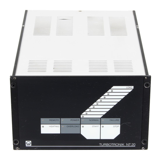
Die Drehzahl jeder TURBOVAC kann im Bedarfsfall durch den LEYBOLD-Kundendienst um ±5% angepasst werden. Die TURBOTRONIK NT 20 sind nach dem Stand der Technik und den anerkannten sicherheitstechnischen Über die an der Rückseite der TURBOTRONIK NT 20 Regeln gebaut. Dennoch können bei unsachgemäßer befindliche Klemmleiste kann die TURBOTRONIK Installation oder nicht bestimmungsgemäßem Gebrauch... - Page 3 Beschreibung TURBOTRONIK NT 20 Abb. 1 Frontseite der TURBOTRONIK NT 20, Erläuterungen siehe Tabellen 1 und 2 Tabelle 1: Betriebszustand-Anzeige durch die LEDs auf der Frontseite Farbe Anzeige LOAD grün LED “START” leuchtet: Drehzahl der TURBOVAC (einzelne LED, lineare Anzeige) (LED Kette) LED “OVERLOAD”...
-
Page 4: Lieferumfang
Beschreibung 1.2 Lieferumfang Steuer-Ausgänge Relais max. 250 V AC, 3 A Elektronischer Frequenzwandler TURBOTRONIK 50 V DC, 2 A (ohmsche Last) NT 20 mit Gehäuse als Tischgerät. für Normalbetrieb Arbeitskontakt für Hochlauf Arbeitskontakt Netzleitung für Störung Wechslerkontakt mit Schutzkontakt-Stecker (Kat.-Nr. 857 20) oder US-Netzstecker (Kat.-Nr. -
Page 5: Bestelldaten
Beschreibung Frontplatte Gehäuse Abb. 2 Maßzeichnung der TURBOTRONIK NT 20, Maße in mm 1.4 Bestelldaten Kat.-Nr. Elektronischer Frequenzwandler TURBOTRONIK NT 20 230 V 857 20 120 V 857 21 100 V 857 22 Verbindungsleitung zur TURBOVAC 3 m lang 857 65... -
Page 6: Anschluss
Anschluss 2 Anschluss 2.2 TURBOVAC anschließen Vorsicht Die Anschlüsse für Vorvakuumpumpe, Küh- Verbindungsleitung zur TURBOVAC bei (3/3) und an der lung, Belüftungsventil und Flanschheizung TURBOVAC einstecken und befestigen. dürfen nur von einem Fachmann entspre- chend den VDE-Richtlinien durchgeführt werden. 2.3 Vorvakuumpumpe Vorsicht anschließen Im Innern der TURBOTRONIK liegen... -
Page 7: Belüftungsventil Anschließen
10 Sicherungen 11 Anschluss für ein Belüftungsventil 12 Anschluss der Netzleitung 13 Sicherung mit Steckfassung für Netzspannungswahl Abb. 3 TURBOTRONIK NT 20, Rückseite 2.5 Belüftungsventil Prozess-Ablaufs der Beginn und die Dauer des Belüf- tungsvorganges eingestellt werden. anschließen Die Einstellzeit lässt sich zwischen 3 bis 15 Minuten vari- ieren. - Page 8 ”-” 16 ACCEL (Hochlauf) 8 HEATING “+” 17 ACCEL (Hochlauf) 18 Option Trigger 19 Option Zwischen- 20 Option kreisstrom Abb. 5 TURBOTRONIK NT 20, Rückseite; Belegung der Klemmleiste (3/5) Tabelle 3 FAILURE FAILURE Relais-Zustand VALVE HEATER FOREPUMP...
-
Page 9: Fernsteuerung Anschließen
Anschluss Klemmen-Nr. Klemmen-Nr. Klemmen-Nr. aktiv = 13 V ... 33 V inaktiv = 0 V ... 7 V aktiv = 0 V ... 7 V inaktiv = 13 V ... 33 V aktiv = 13 V ... 33 V inaktiv = 0 V ... 7 V Passive Ansteuerung mit Kontakten;... -
Page 10: Turbotronik Einbauen
Anschluss 2.8 TURBOTRONIK einbauen Zum Einbau in einen Schaltschrank den Einbaurahmen 19“, 3HE verwenden! Die Wärmeabfuhr der TURBOTRONIK darf nicht behin- dert werden. Für ausreichende Belüftung sorgen. Die Umgebungs-Temperatur darf 45°C bei Betrieb nicht übersteigen. Besonders auf ausreichende Wärmeabfuhr der beiden Seitenprofile achten. Zwei TURBOTRONIK NT 20 können in der Regel nicht nebeneinander in ein 19“-Rack einbebaut werden. -
Page 11: Bedienung Und Betrieb
Bedienung und Betrieb 3 Bedienung und Betrieb 3.1 Inbetriebnahme 3.2 TURBOVAC starten DIP-Schalter-Einstellungen Durch Drücken der Taste START wird der Hochlauf der TURBOVAC ausgelöst, eine evtl. angeschlossene Vor- Es ist erforderlich, die DIP-Schalter auf der Geräte- vakuumpumpe läuft sofort an. Rückseite - “INTERFACE”... -
Page 12: Betrieb
Diese Verschmutzung kann zu Fehlfunktionen, geht aus. Überhitzung oder Kurzschluss führen und muss nach Möglichkeit vermieden werden. Der Leybold-Service Die TURBOVAC läuft bis zum Stillstand aus. kann den Frequenzwandler reinigen. Wir empfehlen Rei- Nach einem Störfall “FAILURE” kann mit der Taste nigungsintervalle von etwa 3 Jahren STOP die Störungsanzeige zurückgesetzt werden, vor-... -
Page 13: Fehlersuche
Verbindungs-Leitung hat Wackelkontakt. Verbindungs-Leitung reparieren. ———————————————————————————————————————————————————————————————— Nr.3 TURBOVAC erreicht nicht Vorvakuum >10 mbar. Vorvakuum überprüfen. die Soll-Drehzahl innerhalb Pumpe blockiert. Leybold-Kundendienst benachrichtigen. von 10 Minuten. Hochvakuumdruck zu hoch. Vakuumbehälter überprüfen. ———————————————————————————————————————————————————————————————— Nr.4 Mindest-Drehzahl wurde Vorvakuum >10 mbar. Vorvakuum überprüfen. unterschritten. -
Page 14: Eg-Konformitätserklärung
EG-Konformitätserklärung Hiermit erklären wir, die Leybold Vakuum GmbH, dass Die Produkte entsprechen folgenden Richtlinien: die nachfolgend bezeichneten Produkte aufgrund ihrer • EG-Niederspannungsrichtlinie (73/23/EWG) Konzipierung und Bauart sowie in der von uns in Verkehr ge-brachten Ausführung den einschlägigen grundlegen- • EG-Richtlinie Elektromagnetische Verträglichkeit... -
Page 15: Ec Conformance Declaration
EC Conformance Declaration We, the Leybold Vacuum GmbH, declare herewith that The products comply with the following guidelines: the products listed below, on the basis of their design • EC Low-Voltage Guidelines (73/23/EEC) and engineering as well as in the embodiment which we have placed on the market, comply with the applicable •... -
Page 16: The English Operating Instructions Start On Page
Maintenance ......26 The TURBOTRONIK NT 20 does not support the pump models TURBOVAC 150 H and TURBOVAC 360 H. - Page 17 Description TURBOTRONIK NT 20 Fig. 1 Front panel of the TURBOTRONIK NT 20, explanation see table 1 and 2 Table 1: Operational Status Display of the Front Panel LEDs Color Display LOAD green LED “START” lights up: speed of the TURBOVAC (individual LED, linear display) LED “OVERLOAD”...
-
Page 18: Standard Specifications
Description 1.2 Standard Specifications Control Outputs Relay max. 250 V AC, 3 A TURBOTRONIK NT 20 table-top electronic frequency 50 V DC, 2 A (resistive load) converter with housing. for normal operation operating contact for acceleration operating contact Power linecord... -
Page 19: Ordering Data
Description Front panel Housing Fig. 2 Dimensional drawing, dimensions in mm 1.4 Ordering Data Cat. No. Electronic frequency converter TURBOTRONIK NT 20 230 V 857 20 120 V 857 21 100 V 857 22 Connection line to the TURBOVAC 3 m long... -
Page 20: Connection
Swit- ching examples are given in fig. 4. The mains voltage setting of the TURBOTRONIK NT 20 A starting delay for the TURBOVAC can be set at (3/6); can be changed; see „Technical Data“. -
Page 21: Connecting The Venting Valve
11 Connection for venting valve 12 Connection for power linecord 13 Plug for selecting the mains voltages with integrated fuse Fig. 3 TURBOTRONIK NT 20, rear panel 2.5 Connecting the Venting ting sequence in order to protect a system or a process- procedure. - Page 22 8 HEATING “+” 17 ACCEL 18 Optional Trigger for link circuit 19 Optional 20 Optional current Fig. 5 TURBOTRONIK NT 20, rear panel; assigment of the terminal strip (3/5) Table 3 FAILURE FAILURE Relay status VALVE HEATER...
-
Page 23: Connecting The Remote Control Unit
Connection Terminals No. Terminals No. Terminals No. active = 13 V ... 33 V inactive = 0 V ... 7 V active = 0 V ... 7 V inactive = 13 V ... 33 V active = 13 V ... 33 V inactive = 0 V ... -
Page 24: Installing The Turbotronik
(113°F). Make sure that there is sufficient heat dissipati- on for the two side profiles. As a general rule, it is not possible to install two TURBOTRONIK NT 20 units in one 19“ rack. If - after installation - the rear of the TURBOTRONIK is no longer accessible, switch on the power switch (3/1) and the DIP switches before mounting and if nec. -
Page 25: Operation
Operation 3 Operation 3.1 Start-up 3.2 Start-up of the TURBOVAC DIP switch settings The DIP switches located at the rear of the unit - “INTER- Pressing the START key initiates the acceleration FACE” - (3/7) must be set to match the respective pump sequence;... -
Page 26: Bake-Out Of The Turbovac
The LEYBOLD Service Department can clean the con- verter. We recommend adhering to a cleaning interval of 3.5 Shut-down of the about three years. -
Page 27: Troubleshooting
The TURBOVAC has not Forevacuum pressure >10 mbar. Check the forevacuum. attained the target speed Pump blocked. Inform the Leybold after-sales service. within 10 minutes. High vacuum pressure too high. Check the vacuum chamber. ———————————————————————————————————————————————————————————————— No. 4 Speed below minimum. - Page 28 LEYBOLD VAKUUM GmbH Bonner Strasse 498 (Bayenthal) D-50968 Köln Tel.: (0221) 347-0 Fax: (0221) 347-1250 http://www.leyboldvac.de e-mail:documentation@leyboldvac.de...
Need help?
Do you have a question about the TURBOTRONIK NT 20 and is the answer not in the manual?
Questions and answers