Table of Contents
Advertisement
Quick Links
General Installation Manual
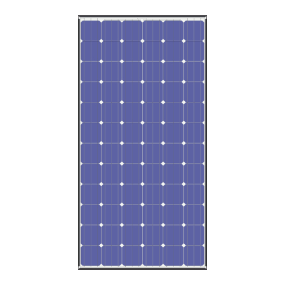
Photovoltaic Module HIT
HIT Power 240S series
HIT Power 235S series
HIT Power 230S series
Thank you for choosing Panasonic HIT
Please read this manual completely
before installation or use of Panasonic
PV(photovoltaic) modules. With proper
operation and maintenance, Panasonic
®
HIT
will
provide
you
renewable solar electricity for many
years. This manual contains important
installation, maintenance and safety
information. The word "module" as
used in this manual refers to one or
more PV modules. Retain this manual
for future reference. The module is
considered to be in compliance with UL
1703 only when the module is mounted
in
the
manner
specified
mounting instructions below.
SANYO is part of the Panasonic Group
and is in charge of the manufacturing
process for Panasonic HIT
VBHNxxxSA series
®
Model No.
HIT Power 240S
VBHN240SA11 and 11B
HIT Power 235S
VBHN235SA11 and 11B
HIT Power 230S
®
.
VBHN230SA11 and 11B
with
clean,
by
the
®
.
Contents
Please read before installation
Note on Specifications
"HIT" is a registered trademark of
Panasonic Group.
Other product and service names listed
in
registered
respective companies.
1
this
manual
are
trademarks
trademarks
of
:3
:3
:3
:3
:3
:4
:4
:5
:5
:5
:5
:5
:5
:5
:6
:6
:8
:8
:8
:8
:8
:8
:8
or
their
Advertisement
Table of Contents

Related Manuals for Panasonic HIT Power 240S


Summary of Contents for Panasonic HIT Power 240S
-
Page 1: Table Of Contents
Grounding Locations mounting instructions below. Grounding Methods Module Terminations SANYO is part of the Panasonic Group Junction Box and Terminals and is in charge of the manufacturing Conduit ® process for Panasonic HIT... - Page 2 Edition Revision Date Revised Item Revised Content New Edition 2013.4.19 (1) Addition of System Fire Class Rating (1) System Fire Class Rating (2) Explanation of trademark Edition 2015.3.18 (2) Trademark (3) According to UL1703 Edition 3 (3) Front cover, Grounding –...
-
Page 3: Safety Precautions
Panasonic. There requirements, which should Safety Precautions are no user serviceable parts within followed. General Information the module or junction box. Electrically ground modules for all installation solar modules Unauthorized persons - except the systems voltage. -
Page 4: Installation General :4
Installation (reference) Please read this guide completely 1.5” before installing using your (38mm) 1.5” Panasonic PV modules. This section Solar Module (38mm) contains important electrical mechanical specifications. Metal clamp B Modules should be firmly fixed in (2 places) place manner... -
Page 5: Operating Conditions :5
National Electric Code warranty for clamps. The module 3) The current output for the modules (690.7) to ensure compliance with warranty Panasonic provides shall be shown SPECIFICATIONS maximum voltage limitations. voided if clamps selected by the section is measured at Standard Test Modules are not designed for “off-... -
Page 6: Grounding Locations :6
Lay-in lugs or grounding clips can be used ground Panasonic modules. Both methods Ground Location explained below, please choose one. (larger holes for bolt and nut) Grounding... - Page 7 Wire connection using cup washers (see In this case, the screw threads are used ILSCO GBL-4DBT, Burndy Figures 3.2 and 3.3) not providing the electrical ground CL501TN. The use of cup washers is to prevent contact. Attach grounding lug to module wire from slipping out from under frame using a stainless steel bolt and the screw head (and/or the flat...
-
Page 8: Module Terminations :8
with modules must As part of Panasonic’s policy of performance of the solar modules. purchased separately. continuous improvement, Panasonic If the module surface becomes dirty, reserves the right to change product it may reduce output power. - Page 9 Glass Figure 3.2 (Method 1) Grounding method using self-tapping machine screw Backsheet Frame (Longer side) Note: Use the smaller ground holes illustrated in Figure 3.1. Grounding hole *If using a brass cup washer, a (0.165’‘ diameter (4.2 mm) ) flat washer must be inserted between the cup washer and module frame,...
- Page 10 Figure 3.4 Glass Frame (Longer side) Grounding method Backsheet Using self-tapping machine screw Note: Use the smaller ground holes illustrated in Figure 3.1. Grounding hole Select a grounding the following (0.165” diameter lug. (4.2mm)) Star washer (Stainless steel) ILSCO GBL-4DBT, Thickness: Burndy CL501TN not less than 0.02”...
- Page 11 Figure 3.6 Grounding method Frame (Longer side) Using Grounding Clip with self- Glass tapping machine screw Backsheet Note: Use the smaller ground holes illustrated in Figure 3.1. Grounding Clip Assemblies: Tyco Grounding hole Electronics 1954381-1. (0.165” diameter (4.2mm)) Self-tapping machine screw (Stainless steel)
- Page 12 SPECIFICATIONS Electrical Specifications Model HIT Power 240S HIT Power 235S HIT Power 230S VBHN240SA11 VBHN235SA11 VBHN230SA11 VBHN240SA11B VBHN235SA11B VBHN230SA11B Cell Number in Series Rated Power, Watts (Pmax) Maximum Power Voltage (Vpm) 43.7 43.0 42.3 Maximum Power Current (Ipm) 5.51 5.48 5.45...
Need help?
Do you have a question about the HIT Power 240S and is the answer not in the manual?
Questions and answers