Advertisement
Quick Links
General Installation Manual
© Feb 2012, SANYO Electric Co., Ltd. All Rights Reserved
General Installation Manual for Panasonic HIT
Modules, manufactured by SANYO. Please read this manual
carefully before installing or using Panasonic modules. This
manual applies to the following HIT Power products:
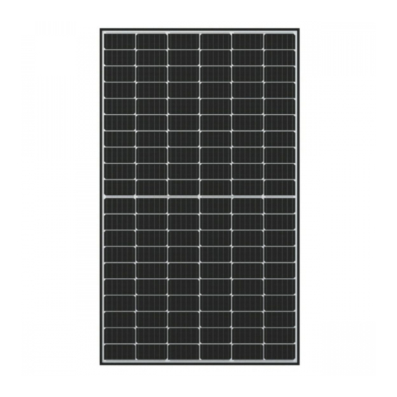
HIT Power 225A (VBHN225AA01)
HIT Power 220A (VBHN220AA01)
HIT Power 215A (VBHN215AA01)
HIT Power 210A (VBHN210AA01)
INTRODUCTION
Thank you for choosing Panasonic HIT photovoltaic (PV) modules.
With proper operation and maintenance, Panasonic HIT PV
modules will provide you with clean, renewable solar electricity for
many
years.
This
manual
maintenance and safety information. The word "module" as used
in this manual refers to one or more PV modules. Retain this
manual for future reference.
Disclaimer of Liability
SANYO does not assume responsibility and expressly disclaims
liability for loss, damage, or expense arising out of, or in any way
connected with installation, operation, use, or maintenance by
using this manual.
SANYO assumes no responsibility for any infringement of patents
or other rights of third parties, which may result from use of
modules.
No license is granted by implication or under any patent or patent
rights. The information in this manual is believed to be reliable, but
does not constitute an expressed and/or implied warranty.
SANYO reserves the right to make changes to the product,
specifications, data sheets and this manual without prior notice.
General Information
The installation of solar modules requires a great degree of skill
and should only be performed by qualified licensed professionals,
including, without limitation, licensed contractors and electricians.
WARNING
•
All instructions should be read and understood before
attempting to install, wire, operate, and maintain a
photovoltaic module.
•
Contact with electrically active parts of the module such
as terminals can result in burns, sparks, and lethal shock
whether the module is connected or disconnected.
•
The installer assumes the risk of all injury that might
occur during installation, including, without limitation, the
risk of electric shock.
•
PV modules generate DC (direct current) electrical energy
when exposed to sunlight or other light sources. Even a
single module produces enough voltage and current, to
cause shocks and burns if safety precautions are not
followed.
•
The shock hazard increases as modules are connected in
parallel, producing higher current, and as modules are
connected in series, producing higher voltages.
•
To avoid the hazard of electric sparks, shock, fire, burns,
damage and injury:
• Work only in dry conditions, with dry modules and dry
tools.
• Do not stand or step on modules. Do not puncture, cut,
scratch or damage the backsheet of a module.
Backsheet damage will void a module's Limited
®
Photovoltaic
contains
important
installation,
Warranty and may cause fire. Never use modules with a
damaged back sheet.
• Do not allow children and unauthorized persons near
the installation or storage site of modules.
• Completely ground all modules.
• Do not disassemble a module, attempt any repair, open
the junction box cover, nor remove any parts installed
by Sanyo. There are no user serviceable parts within
the module or junction box.
• Unauthorized persons - except the qualified licensed
professional - should not perform any electrical work,
including wiring,
• Wear suitable clothing, guards, eye protection and
gloves to prevent you from direct contact with 30 VDC
or greater.
• Wear non-slip gloves and carry modules by the frame
using both hands. Do not attempt to carry a module by
yourself.
• Do not carry a module by its wires or junction box.
• Do not drop anything on the surface of a module.
• Ensure all system components are compatible, and
they do not subject the module to mechanical or
electrical hazards.
• Sparks may occur; do not install modules where
flammable gases or vapors are present.
• Never rest or leave a module unsupported or
unsecured.
• Do not drop modules.
• Do not use or install broken modules.
• Do not artificially concentrate sunlight on a module.
• Do not touch the junction box terminals.
• Do not change the wiring of bypass diodes.
• Do not touch a PV module unnecessarily. The glass
surface and frames get hot. There is a risk of burn.
CAUTIONS
•
Use a module for its intended purpose only.
•
Do not treat the back sheet, frame, or front surface with
paint or adhesives, to avoid reducing its' functionality,
damage, and causing inoperable conditions, and other
unknown troubles.
GENERAL SAFETY
Follow
all
permissions,
requirements.
•
Before installing modules, contact the appropriate authorities
having jurisdiction to determine permissions, installation and
inspection requirements, which should be followed.
•
Electrically ground modules for all systems of any voltage. If
not otherwise specified, it is recommended that requirements
of the latest National Electrical Code (USA) or Canadian
Electric Code (Canada) or other national or international
electrical standards be followed. Refer to "Earth Ground
Wiring" section for more information.
•
Be sure that the building or structure (roof, façade, etc.) where
the modules are being installed has enough strength to
support the load of the modules.
•
For modules mounted on roofs, special structures may be
required to help provide proper installation support.
•
Both, roof construction and module installation design have an
effect on the fire resistance of a building. Improper installation
1
installation
and
inspection
Advertisement

Related Manuals for Panasonic HIT Power 225A


Summary of Contents for Panasonic HIT Power 225A
- Page 1 INTRODUCTION • Unauthorized persons - except the qualified licensed Thank you for choosing Panasonic HIT photovoltaic (PV) modules. professional - should not perform any electrical work, With proper operation and maintenance, Panasonic HIT PV including wiring, modules will provide you with clean, renewable solar electricity for •...
-
Page 2: Specifications
Average High or Low of the installation site. Please read this guide completely before installing or using your The wind pressure load of the installation site should be less Panasonic PV modules. This section contains important electrical than 2,880N/m (60PSF) and mechanical specifications.. - Page 3 General Installation Manual © Feb 2012, SANYO Electric Co., Ltd. All Rights Reserved time of shipment, Sanyo guarantees the output level of its • These modules contain factory installed bypass diodes. If modules -0/+10% against Rated Power these modules are incorrectly connected to each other, the SPECIFICATIONS based on Sanyo’s factory inspection at bypass diodes, cable, or junction box may be damaged.
- Page 4 General Installation Manual © Feb 2012, SANYO Electric Co., Ltd. All Rights Reserved All fasteners (nuts, bolts, washers, screws, etc.) must be stainless steel is inserted between the module frame and the stainless steel unless otherwise specified. cup washer. • •...
- Page 5 General Installation Manual © Feb 2012, SANYO Electric Co., Ltd. All Rights Reserved • • If using this method, please follow instructions in previous In order to comply with NEC 2008, a locking sleeve needs to section regarding using bolts and nuts with larger grounding be used with all connectors that are exposed.
-
Page 6: Maintenance
SANYO. As part of SANYO’s policy of continuous improvement, SANYO reserves the right to change product specifications at any time without prior notice. further information, please visit http://panasonic.net/energy/solar/ or contact your SANYO Authorized Representative. - Page 7 General Installation Manual © Feb 2012, SANYO Electric Co., Ltd. All Rights Reserved Glass Figure 3.2 (Method 1) Grounding method using self-tapping screw Backsheet Frame (Longer side) Note: Use the smaller ground holes illustrated in Figure 3.1. Grounding hole (0.165’‘ diameter (4.2 mm) ) *Flat washer (Stainless steel) Cup washer (Terminal cup) (Stainless steel or *brass)
- Page 8 General Installation Manual © Feb 2012, SANYO Electric Co., Ltd. All Rights Reserved Glass Frame (Longer side) Figure 3.4 Backsheet Grounding method Using self-tapping screw Note: Use the smaller ground Grounding hole holes illustrated in Figure 3.1. (0.165” diameter (4.2mm)) Select grounding following lug.
- Page 9 General Installation Manual © Feb 2012, SANYO Electric Co., Ltd. All Rights Reserved Figure 3.6 Grounding method Frame (Longer side) Using Grounding Clip with Glass self-tapping screw Backsheet Note: Use the smaller ground holes illustrated in Figure 3.1. Grounding hole (0.165”...
- Page 10 General Installation Manual © Feb 2012, SANYO Electric Co., Ltd. All Rights Reserved SPECIFICATIONS Electrical Specifications Model HIT Power 225A HIT Power 220A HIT Power 215A HIT Power 210A (VBHN225AA01) (VBHN220AA01) (VBHN215AA01) (VBHN210AA01) Cell Number in Series Rated Power, Watts (Pmax) Maximum Power Voltage (Vpm) 43.4...
Need help?
Do you have a question about the HIT Power 225A and is the answer not in the manual?
Questions and answers