
Related Manuals for Beijer Electronics QTERM-G70


Summary of Contents for Beijer Electronics QTERM-G70
- Page 1 ® LARITY ASED ERMINAL ARDWARE ANUAL BEIJER ELECTRONICS 1865 West 2100 South Salt Lake City, Utah 84119 Phone 801-466-8770 Fax 801-466-8792 Email info@BeijerInc.com http://www.BeijerInc.com M01-004-00 Rev 06...
- Page 2 Copyright © 2013 Beijer Electronics. Printed in the USA. All rights reserved. No part of this publication may be reproduced, in any form or by any means with- out prior written permission from Beijer Electronics. Qlarity and QTERM are registered trademarks of Beijer Electronics.
- Page 3 Any modification to this device (including any changes to the recommended antenna configuration) that are not expressly approved by Beijer Electronics could void the user’s authority to operate this device. Additionally, these devices may contain the following FCC module-certified components depending on product configuration:...
-
Page 5: Table Of Contents
ONTENTS 1. QTERM-G70 T .........1... - Page 6 Contents 2.3.5 Real-Time Clock..........25 2.3.6 System Memory .
- Page 7 Contents 4. QTERM-G56 T ........49 HAPTER ERMINAL 4.1 Product Description .
- Page 8 Contents 5.3.1 Display ............68 5.3.2 Touch Screen .
- Page 9 Contents 7.4.4 Powering On the Terminal for the First Time ......96 8. P ..........97 HAPTER OWER ETUP...
- Page 10 Contents 8.4.12.1 Information ..........118 8.4.12.2 Use Password.
- Page 11 Figure 4, QTERM-G70 Standard Key Legend........
- Page 12 Figures Figure 37, QTERM-G72 3-Pin Terminal Strip ........89 Figure 38, QTERM-G72 Landscape Cutout .
-
Page 13: Hapter
The QTERM-G70 terminal requires a DC power source in a range of 8 to 26 VDC. This power is supplied via the main DB9 serial connector. Other options for supplying power to the QTERM-G70 are PoE (Power-over-Ethernet) and five volts from a well-regulated power sup- ply via the main DB9 serial connector. -
Page 14: Specifications
Product Description QTERM-G70 Terminal 1.1.1 Specifications The following tables contain the technical specifications for the QTERM-G70. TERMINAL DISPLAY Color (standard) STN 256 colors Grayscale (optional) FSTN 16 shades of gray Active Matrix (optional) TFT 256 colors Enhanced TFT (optional) Enhanced TFT 256 colors... - Page 15 Shock 20 g, 3 ms, any axis POWER 8 to 26 VDC (See section 1.4.5 for current consumption) PoE (Power-over-Ethernet) Well-regulated 5V supply (contact Beijer Electronics) SOFTWARE Programming language Qlarity® (object-based) Design environment Qlarity Foundry (Windows®) Command line compiler Qlarify (Win32 or Linux®)
-
Page 16: Supported Interfaces
1.2 Supported Interfaces 1.2.1 Serial Ports The QTERM-G70 comes standard with one serial port with DB9f connector. The serial port interface can be EIA-232, EIA-422, or EIA-485. A second serial port is available as an option, as well as two or four additional full EIA-232 serial ports are also optional. -
Page 17: Optional Ethernet Port
Figure 2 QTERM-G70 Ethernet Port Pinouts 1.2.3 Optional PS/2 Keyboard Interface The optional PS/2 port can be used to connect a standard PS/2 keyboard to the QTERM-G70 terminal. The connector orientation and pinout table are shown in Figure 3. Figure 3 QTERM-G70 PS/2 Keyboard Interface Pinouts PS/2 keyboard interface is not available in the terminals with the PoE option. -
Page 18: Optional Dual And Quad Eia-232 Serial Port Card
QTERM-G70 Terminal 1.2.5 Optional Dual and Quad EIA-232 Serial Port Card An additional two or four EIA-232 serial ports can be added to the QTERM-G70. These serial ports have all necessary signals for EIA-232 serial communications and are wired as Data Terminal Equipment (DTE). -
Page 19: Pinouts
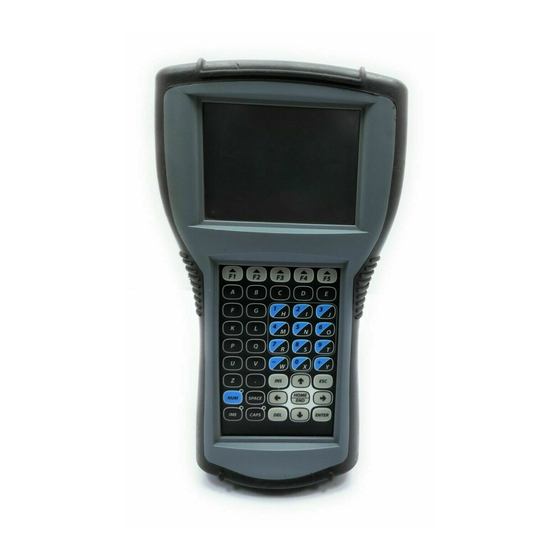
1.3 Terminal Components 1.3.1 Touch Screen The QTERM-G70 touch screen provides user input through any number of touch keys located on or around the display. The standard key legend shown in Figure 4 provides areas for five soft keys down each side of the display. A custom legend underlay can be ordered to personal- ize the terminal for your application. -
Page 20: Keyboard
1.3.3 Keypad The QTERM-G70 terminal can optionally include electronics for attaching an external keypad with up to 8 columns by 8 rows and up to 6 keypad LEDs. Contact Beijer Electronics for more information. The keypad option will add 10 mA to the total current draw of the terminal plus the current driven out the LED outputs pins. -
Page 21: Speaker
Col 7 1.3.4 Speaker A speaker is built into the QTERM-G70 terminal and faces to the back of the unit. Audio can be linked to events or actions (e.g., screen press, timer, etc.). Pitch and duration of a sound are controlled by API functions called from the user application. -
Page 22: Watchdog Timer
1.4.1 Cutout for Panel Mount Configuration The QTERM-G70 terminal can be mounted in panels from 0 to 7 mm thick. No screw holes need to be drilled to install the terminal in the panel. Make a rectangular hole in the panel using the following dimensions. -
Page 23: Installing The Panel Mount Terminal
Installing to NEMA-4 Figure 5 is a diagram of the landscape cutout. Figure 5 QTERM-G70 Landscape Cutout File any rough edges smooth, especially on the face of the panel. 1.4.2 Installing the Panel Mount Terminal Use of an anti-static strap is recommended when performing installation and maintenance. -
Page 24: Figure 6 Qterm-G70 Front Panel Mount
Installing to NEMA-4 QTERM-G70 Terminal Figure 6 QTERM-G70 Front Panel Mount 3. On the back of the panel, place the terminal mounting bracket against the back of the ter- minal, and align it with the back panel. Refer to Figure 7. -
Page 25: Cutout For Drywall Mount Configuration
Installing to NEMA-4 1.4.3 Cutout for Drywall Mount Configuration The QTERM-G70 terminal with the drywall mount configuration will accommodate drywall thicknesses of 7 mm to 18 mm. The panel may be cut by using the template supplied with the unit or by using the dimensions given below. To use the template, simply identify where the unit is to be placed on the wall and tape the template up into position. -
Page 26: Removing The Drywall Mount Terminal
3. Gently pull the terminal from the wall cutout. 1.4.5 Applying Power Power is supplied to the QTERM-G70 terminal via the primary serial port connector. Refer to section 1.2.1, “Serial Ports” for power and ground pin assignments. DC power must be in the range of 8 to 26 volts (the current will vary depending on the input voltage;... -
Page 27: Powering On The Terminal For The First Time
20 mA 1.5 Powering On the Terminal for the First Time When you connect power to the QTERM-G70 terminal, it automatically loads the application saved in flash memory into RAM memory and executes the application. If no application is present, the terminal display may be blank but the backlighting verifies it is powered on. - Page 28 Powering On the Terminal for the First Time QTERM-G70 Terminal Notes Qlarity-Based Terminal Hardware...
-
Page 29: Hapter
DB9 serial connector. Other options for supplying power to the QTERM-G75 are PoE (Power-over-Ethernet) or five volts from a well-regulated power supply via the main DB9 serial connector. Please contact Beijer Electronics for more information about this option. -
Page 30: Specifications
Product Description QTERM-G75 Terminal 2.1.1 Specifications The following tables contain the technical specifications for the QTERM-G75. TERMINAL DISPLAY Active Matrix (standard) TFT 256 colors Enhanced TFT (optional) Enhanced TFT 256 colors Pixels 640 x 480 Dot pitch 0.33 mm Dual lamp cold-cathode fluorescent, brightness software-con- Lighting trollable Backlight brightness... - Page 31 QTERM-G75 Terminal Product Description SPEAKER Standard Software programmable pitch and duration Optional Audio (.wav) decoder REAL-TIME CLOCK Independent processor-based, real-time clock equipped with a battery backup PHYSICAL Configuration Panel-mount Aluminum, accommodates panels from 0 to 12 mm thick with standard Housing screws Size...
-
Page 32: Supported Interfaces
Supported Interfaces QTERM-G75 Terminal 2.2 Supported Interfaces 2.2.1 Serial Ports The QTERM-G75 comes standard with one serial port with DB9f connector. The serial port interface can be EIA-232, EIA-422, or EIA-485. A second serial port is available as an option, as well as two or four additional full EIA-232 serial ports are also optional. -
Page 33: Optional Ethernet Port
QTERM-G75 Terminal Supported Interfaces 2.2.2 Optional Ethernet Port The optional Ethernet port has a standard 10/100Base-T interface with an 8-pin (RJ-45) modu- lar jack connector and uses TCP/IP protocol. The connector orientation and pinout table are shown in Figure 10. Figure 10 QTERM-G75 Ethernet Port Pinouts 2.2.3 Optional PS/2 Keyboard Interface... -
Page 34: Optional Dual And Quad Eia-232 Serial Port Card
Terminal Components QTERM-G75 Terminal 2.2.5 Optional Dual and Quad EIA-232 Serial Port Card An additional two or four EIA-232 serial ports can be added to the QTERM-G75. These serial ports have all necessary signals for EIA-232 serial communications and are wired as Data Terminal Equipment (DTE). -
Page 35: Keyboard
2.3.3 Keypad The QTERM-G75 terminal can optionally include electronics for attaching an external keypad with up to 8 columns by 8 rows and up to 6 keypad LEDs. Contact Beijer Electronics for more information. The keypad option will add 10 mA to the total current draw of the terminal plus the current driven out the LED outputs pins. -
Page 36: Speaker
Terminal Components QTERM-G75 Terminal Connector J1 - 0.1 Inch Pitch 16-pin Single-row Connector Row 5 LED 1 Row 6 Row 1 Col 1 Row 2 Col 2 Row 3 Col 3 Row 4 Col 4 Col 5 LED 2 Col 6 Connector J2 - 0.1 Inch Pitch 24-pin Dual-row Connector Row 1... -
Page 37: Real-Time Clock
QTERM-G75 Terminal Installing to NEMA-4 Specifications 2.3.5 Real-Time Clock The QTERM-G75 terminal is equipped with a battery-backed, real-time clock. The real-time clock can be used to time/date stamp messages or for timed polling and program execution. ARNING There may be danger of leakage if the battery is incorrectly replaced, creating a potential health hazard. -
Page 38: Cutting Out The Panel
Installing to NEMA-4 Specifications QTERM-G75 Terminal • Cut a hole in the panel and drill the mounting holes. See section 2.4.1, “Cutting Out the Panel” for specifications. • Install the QTERM-G75 terminal in the panel. See section 2.4.2, “Installing the Terminal” for instructions. -
Page 39: Installing The Terminal
QTERM-G75 Terminal Installing to NEMA-4 Specifications 2.4.2 Installing the Terminal Take the following steps to install the terminal. 1. Verify that the panel surface around the cutout and mounting holes is clean and free of rough edges. A gasket built into the terminal will seal against this surface. Dirt or imper- fections on the panel may prevent a proper seal. -
Page 40: Applying Power
DC power and be limited to a maximum of 26 volts DC. Limiting may be inherent to the supply or may be provided by supplementary overcurrent devices. If the QTERM-G75 does not respond or exhibits abnormal behavior on power up, disconnect power and contact Beijer Electronics for technical support. Qlarity-Based Terminal Hardware... -
Page 41: Powering On The Terminal For The First Time
QTERM-G75 Terminal Installing to NEMA-4 Specifications Current Consumption Terminal 12 VDC 24 VDC Standard unit idle 950 mA 475 mA Enhanced unit idle 1.0 A 500 mA Standard unit, active add 100 mA add 60 mA Enhanced unit, active add 100 mA add 60 mA With keyboard option and keyboard attached add 70 mA... - Page 42 Installing to NEMA-4 Specifications QTERM-G75 Terminal Notes Qlarity-Based Terminal Hardware...
-
Page 43: Hapter
HAPTER QTERM-G55 T ERMINAL 3.1 Product Description The QTERM-G55 is a rugged, handheld or panel-mount Ethernet-enabled graphic terminal with object-based programming. It features a robust list of industrial grade hardware features and options. The QTERM-G55 features a QVGA, 320x240 pixel, LCD transflective FSTN, grayscale (16 shades) display or optional active-matrix TFT (256 colors) display. -
Page 44: Specifications
Product Description QTERM-G55 Terminal 3.1.1 Specifications The following tables contain the technical specifications for the QTERM-G55. TERMINAL DISPLAY Grayscale (standard) FSTN 16 shades of gray Active Matrix Color (optional) TFT 256 colors Pixels 320 x 240 FSTN 0.24 mm Dot Pitch TFT 0.227 mm FSTN Contrast Software-controlled, temperature compensated... - Page 45 QTERM-G55 Terminal Product Description MEMORY Standard 2 Mbytes flash and 16 Mbytes SDRAM SPEAKER Standard Software programmable pitch and duration Optional Audio (.wav) decoder REAL-TIME CLOCK Optional Independent processor-based, real-time clock equipped with a battery backup PHYSICAL Panel-mount Configuration Handheld Handheld - ABS/bicarbonate case with molded rubber boot Housing Panel-mount - ABS/poly carbonate case with rubber overmold trim...
-
Page 46: Supported Interfaces
Supported Interfaces QTERM-G55 Terminal CUSTOMIZING Keypad legend Customize with logo/name or graphics CERTIFICATION FCC Part 15, Class B (Class A with Ethernet or PoE option) CE Certification 3.2 Supported Interfaces 3.2.1 Handheld Connector Interface The QTERM-G55 handheld terminal comes standard with one serial port through a 12-pin round connector (Hirose HR30-8R-12SC) or integral cable with strain relief, terminated with a DB15f connector. -
Page 47: Power Interface
QTERM-G55 Terminal Supported Interfaces 3.2.1.1 Power Interface The following table shows the pinout for each type of power interface. Regulated (standard) 5 Volt Unregulated Power-over-Ethernet 8 - 32 VDC 4.5 - 5.5 VDC No connect Ground Ground Ground No connect No connect PoE V+ No connect... -
Page 48: Power Interface With E-Stop Option
Supported Interfaces QTERM-G55 Terminal 3.2.1.4.1 Power Interface with E-stop Option The following table shows the pinout for each type of power interface when the E-stop option is selected. Regulated 5 Volt Power-over-Ethernet (standard) Unregulated 8 - 32 VDC 4.5 - 5.5 VDC No connect Ground Ground... -
Page 49: Integral Cable
QTERM-G55 Terminal Supported Interfaces Round Connector Pin Wire Color Twisted Pairs Brown Red with Black Stripe Orange Yellow Green with Black Stripe Blue Black Pair #1 White Pair #1 Pair #2 Green Pair #2 Violet Gray No Connect White with Red Stripe Pair #3 No Connect White with Green Stripe... -
Page 50: Power Interface With Integral Cable
Supported Interfaces QTERM-G55 Terminal 3.2.1.6.1 Power Interface with Integral Cable The following table shows the pinout for each type of power interface when the integral cable option is selected. Regulated DB15f Pin 5 Volt Unregulated Power-over-Ethernet (standard) 8 - 32 VDC 4.5 - 5.5 VDC No connect Ground... -
Page 51: Power Interface With E-Stop Option And Integral Cable
QTERM-G55 Terminal Supported Interfaces 3.2.1.7.1 Power Interface with E-stop Option and Integral Cable The following table shows the pinout for each type of power interface when the E-stop option and integral cable are selected. Regulated DB15f Pin 5 Volt Unregulated Power-over-Ethernet (standard) 8 - 32 VDC... -
Page 52: Panel-Mount Connector Interface
Supported Interfaces QTERM-G55 Terminal DB15f Pin Wire Color Twisted Pairs Red with Black Stripe White with Red Stripe Pair #3 White with Green Stripe Pair #3 Blue Yellow Pair #2 Black Pair #1 Gray Brown Drain Orange Green with Black Stripe Green Pair #2 No 14... -
Page 53: Optional Ethernet Port (Panel-Mount)
QTERM-G55 Terminal Supported Interfaces The following table shows the pinouts for each type of serial interface. — RTx- RTx+ — — — — Ground Ground Ground — — CTS (in) — RTS (out) — Power Power Power Power is supplied to the terminal through pin 9 and ground is supplied through pin 5 of the pri- mary serial port connector. -
Page 54: Power Requirements
The QTERM-G72 electronics are packaged in a rugged and attractive black thermoplastic NEMA-4X housing which accommodates the same panel cutout as our QTERM-G70 termi- nal. Optional pad printing of the front bezel with logo/name or graphics is available as an option. -
Page 55: Terminal Components
QTERM-G55 Terminal Terminal Components yields four possible ways to apply power to the PoE port as shown in the following table. The table also shows the conductor assignment for the transmit and receive lines as a reference. Port Pin Assignment Conductor Data PoE V+... -
Page 56: Keypad
Terminal Components QTERM-G55 Terminal The QTERM-G55 may be optionally equipped with a color QVGA, 320x240 pixel, active-matrix TFT LCD (256 colors). It also uses a light emitting diode (LED) backlight, with a typical brightness of 200 nits. 3.3.2 Keypad User input occurs through a rugged 24-key or 40-key membrane keypad with steel snap domes. -
Page 57: Real-Time Clock
QTERM-G55 Terminal Installing to NEMA-4 Specifications 3.3.4 Real-Time Clock The QTERM-G55 terminal can be optionally equipped with a battery-backed, real-time clock. The real-time clock can be used to time/date stamp messages or for timed polling and program execution. ARNING There may be danger of leakage if the battery is incorrectly replaced, creating a potential health hazard. -
Page 58: Cutout For Panel Mount Configuration
Installing to NEMA-4 Specifications QTERM-G55 Terminal 3.4.1 Cutout for Panel Mount Configuration The QTERM-G55 terminal can be mounted in panels from 0 to 7 mm thick. No screw holes need to be drilled to install the terminal in the panel. Make a rectangular hole in the panel using the following dimensions. -
Page 59: Applying Power
DC power and be limited to a maximum of 32 volts DC. Limiting may be inherent to the supply or may be provided by supplementary overcurrent devices. If the QTERM-G55 does not respond or exhibits abnormal behavior on power up, disconnect power and contact Beijer Electronics for technical support. Current Consumption Terminal... - Page 60 Installing to NEMA-4 Specifications QTERM-G55 Terminal Once you have verified that the terminal is functioning properly, refer to Chapter 8, “Power On Setup” for information on configuring your terminal. The Power On Setup utility includes functions to do the following: •...
-
Page 61: Qterm-G56 Terminal
HAPTER QTERM-G56 T ERMINAL 4.1 Product Description The QTERM-G56 is a rugged handheld color LCD graphic terminal with object-based pro- gramming. It features a robust list of industrial-grade hardware features and options, including wired Ethernet. The QTERM-G56 features a QVGA (320x240 pixel) transflective color TFT liquid crystal dis- play (LCD, 256 colors) with integrated 4-wire analog-resistive touch screen. -
Page 62: Specifications
Product Description QTERM-G56 Terminal Other features include a speaker with software-controlled note pitch, duration, and volume. The terminal may optionally include an audio decoder for .wav file playback. All units feature a real-time clock with one second resolution and battery backup power. The terminal may optionally include an integral cable. - Page 63 QTERM-G56 Terminal Product Description INTERFACE (continued) 7 or 8 data bits 1 or 2 stop bits Data formats Even, odd, or no parity (Development tools support only 8 data bits) 12-pin round (Hirose HR30-8R-12SC) Connector Integral cable with DB15f (optional) Ethernet (optional) 10/100Base-T with support for TCP/IP USB 2.0 full speed (12 megabits/second) for access to internal...
-
Page 64: Supported Interfaces
Supported Interfaces QTERM-G56 Terminal SOFTWARE Programming language Qlarity (object-based) Design environment Qlarity Foundry (Windows) Command line compiler Qlarify (Win32 or Linux) CUSTOMIZING Keypad legend Customize with logo/name or graphics CERTIFICATION FCC Part 15, Class A CE Certification 4.2 Supported Interfaces 4.2.1 Connector Interface The QTERM-G56 handheld terminal comes with one serial multiprotocol port through a 12-pin round connector (Hirose HR30-8R-12SC) or integral cable with strain relief, termi-... -
Page 65: Power And Usb Device Interfaces
QTERM-G56 Terminal Supported Interfaces 4.2.1.1 Power and USB Device Interfaces The following table shows the pinout for the power and USB device interfaces. Regulated PC USB (standard) Host Port 8 - 32 VDC 4.5 - 5.5 VDC Ground Ground USB D+ USB D- 4.2.1.2 Serial Multiprotocol Port Interface The following table shows the connector pinout for the selected type of serial interface on the... -
Page 66: Accessory Cable Wire Color Code And Demo Cable Pinout
Supported Interfaces QTERM-G56 Terminal 4.2.1.5 Accessory Cable Wire Color Code and Demo Cable Pinout The following table shows the wire color code for the 12-pin round connector to unterminated (“blank”) accessory cable and the pinout to the demo cable, which terminates in a 15-pin female D subminiature connector (DB15f);... -
Page 67: Power And Usb Device Interfaces With Integral Cable
QTERM-G56 Terminal Supported Interfaces Figure 23 QTERM-G56 Integral Cable Connector 4.2.2.1 Power and USB Device Interfaces with Integral Cable The following table shows the pinout for the power and USB device interfaces when the inte- gral cable option is selected. DB15f Pin Regulated (standard) 5 Volt USB Host... -
Page 68: Network Interface With Integral Cable (With Ethernet Option)
Supported Interfaces QTERM-G56 Terminal 4.2.2.4 Network Interface with Integral Cable (with Ethernet option) The following table shows the pinout for the 10/100Base-T network interface. DB15f Pin Ethernet 4.2.2.5 E-stop Option with Integral Cable If the terminal is equipped with the E-stop option (which requires the integral cable), the DB15f pinout changes to accommodate the switch signals, as shown below. -
Page 69: Ethernet Option)
QTERM-G56 Terminal Supported Interfaces 4.2.2.8 Additional Serial Interface with E-Stop Option and Integral Cable (without Ethernet option) The following table shows the pinout for the EIA-232 serial interface with integral cable and E-stop option. EIA-232 4.2.2.9 Network Interface with E-Stop Option and Integral Cable (with Ethernet option) The following table shows the pinout for the 10/100Base-T network interface with integral cable and E-stop option. -
Page 70: Integral Cable Wire Color Code
Terminal Components QTERM-G56 Terminal 4.2.2.12Integral Cable Wire Color Code The following table shows the wire color code for the DB15f connector on the integral cable; this information is provided to facilitate removal of the DB15f if desired. Ten of the fifteen conductors in the cable are wired as 100 ohm twisted pairs, as shown in the table. -
Page 71: Touch Screen
QTERM-G56 Terminal Terminal Components Figure 24 QTERM-G56 Display 4.3.2 Touch Screen The QTERM-G56 touch screen provides user input through any number of touch keys located on the display. Touch keys can be defined in your user applications at any location on the dis- play and may be any size. -
Page 72: Real-Time Clock
Terminal Components QTERM-G56 Terminal The terminal may optionally include an audio decoder that allows the terminal to play PCM audio (.wav) files. The audio decoder supports wave files meeting the following criteria: • Sample rate of 8 kHz, 11.025 kHz, 16 kHz or 22.050 kHz •... -
Page 73: Applying Power
DC power and be limited to a maximum of 32 volts DC. Limiting may be inherent to the supply or may be provided by supplementary overcurrent devices. If the QTERM-G56 does not respond or exhibits abnormal behavior on power up, disconnect power and contact Beijer Electronics for technical support. Current Consumption Terminal... -
Page 74: Accessing The Internal Mass Storage Via Usb
Powering On the Terminal for the First Time QTERM-G56 Terminal • Select the application mode • Set up communications settings for the terminal • Adjust display backlight • Enter network (Ethernet) settings • Enter/change password (if used) • Set the real-time clock •... -
Page 75: Hapter
HAPTER QTERM-G58 T ERMINAL 5.1 Product Description The QTERM-G58 is a rugged handheld color LCD graphic terminal with object-based pro- gramming. It features a robust list of industrial-grade hardware features and options, including wireless (802.11b/g) Ethernet and battery power. The QTERM-G58 features a QVGA (320x240 pixel) transflective color TFT liquid crystal dis- play (LCD, 256 colors) with integrated 4-wire analog-resistive touch screen. -
Page 76: Specifications
Product Description QTERM-G58 Terminal The QTERM-G58 terminal includes a switching power supply with a wide input voltage range of 8 to 32 VDC. Typically, power is supplied through the 12-pin circular push-lock connector or integral cable. The unit may also be powered from a 5 volt USB host port – in this case, the optional 802.11b/g wireless Ethernet interface is not accessible due to USB power supply lim- itations. - Page 77 QTERM-G58 Terminal Product Description INTERFACE (continued) 7 or 8 data bits 1 or 2 stop bits Data formats Even, odd, or no parity (Development tools support only 8 data bits) Connector 12-pin round (Hirose HR30-8R-12SC) 802.11b/g Infrastructure or Ad Hoc mode Wireless Ethernet (optional) Encryption: 128-bit WEP, WPA, WPA2 (TKIP/AES) Dual internal antennas for receive diversity...
-
Page 78: Supported Interfaces
Supported Interfaces QTERM-G58 Terminal POWER 8 to 32 VDC (See section 5.3.7 for current consumption) 5 VDC USB Host Port (Wireless Ethernet disabled) SOFTWARE Programming language Qlarity (object-based) Design environment Qlarity Foundry (Windows) Command line compiler Qlarify (Win32 or Linux) CUSTOMIZING Keypad legend Customize with logo/name or graphics... -
Page 79: Power And Usb Device Interfaces
QTERM-G58 Terminal Supported Interfaces 5.2.1.1 Power and USB Device Interfaces The following table shows the pinout for the power and USB device interfaces. Regulated PC USB (standard) Host Port 8 - 32 VDC 4.5 - 5.5 VDC Ground Ground USB D+ USB D- 5.2.1.2 Serial Multiprotocol Port Interface The following table shows the connector pinout for the selected type of serial interface on the... -
Page 80: Terminal Components
Terminal Components QTERM-G58 Terminal Round Demo Cable Wire Color Twisted Pairs Connector Pin DB15f Pin Yellow Pair #4 Blue Pair #4 Orange Pair #5 Gray Pair #5 No Connect Violet – No Connect Green with Black Stripe – No Connect Drain –... -
Page 81: Keypad
QTERM-G58 Terminal Terminal Components 5.3.3 Keypad User input occurs through a rugged 24-key or 40-key membrane keypad with steel snap domes. The top row of keys are commonly used as soft keys to navigate through a set of changing menus at the bottom of the display. The standard keypad comes with four or five LEDs under the soft keys that can be used as status or alarm indicators. -
Page 82: System Memory
DC power and be limited to a maximum of 32 volts DC. Limiting may be inherent to the supply or may be provided by supplementary overcurrent devices. If the QTERM-G58 does not respond or exhibits abnormal behavior on power up, disconnect power and contact Beijer Electronics for technical support. Current Consumption Terminal... -
Page 83: Powering On The Terminal For The First Time
• Adjust settings for the keypad and keypad backlight (if available) 5.4.1 Powering and Charging the Battery Powered QTERM-G58 The QTERM-G58 internal battery pack is not user-serviceable. Contact Beijer Electronics ARNING for battery service or replacement. DO NOT attempt to remove the battery pack from the terminal housing. -
Page 84: Accessing The Internal Mass Storage Via Usb
The internal battery is charged by connecting a 12 VDC supply and ground to the power pins of the terminal. Beijer Electronics offers charging cable accessories for standard AC mains power (with optional international plug kit) and a vehicle cigarette lighter adapter. If the termi- nal is powered off at connection, the power and shift LEDs on the keypad will light, and the display will show a battery charging icon. -
Page 85: Hapter
HAPTER QTERM-Z60 T ERMINAL 6.1 Product Description The QTERM-Z60 terminal is an economical graphic terminal with object-based programming. Two different models of the QTERM-Z60 exist to suit any environment and budget. In general, the Z60/H version is NEMA-4 rated and has a user-selectable serial port while the Z60/L is NEMA-12 rated, has one EIA-232 serial port and a slightly different display. - Page 86 Product Description QTERM-Z60 Terminal TERMINAL DISPLAY Lighting Cold-cathode fluorescent, brightness is software-controllable Backlight Brightness 200 nits typical TOUCH SCREEN Analog-resistive operation Transparent touch area over viewable display Labeled touch underlay area on each side of display INTERFACE Z60/H EIA-232, -422 or -485 serial port Z60/L EIA-232 serial port Baud rates...
-
Page 87: Supported Interfaces
QTERM-Z60 Terminal Supported Interfaces ENVIRONMENTAL Vibration 5 to 5000 Hz, 4 g RMS Shock 20 g, 3 ms, any axis POWER 8 to 32 VDC (See section 6.4.3 for current consumption) SOFTWARE Programming language Qlarity (object-based) Design environment Qlarity Foundry (Windows) Command line compiler Qlarify (Win32 or Linux) CERTIFICATION... -
Page 88: Five Volt Power Supply Output
Supported Interfaces QTERM-Z60 Terminal Figure 27 shows the serial connector’s orientation. Figure 27 QTERM-Z60 Serial Connector with proper cables and grounding the terminal can communicate up to EIA-232 five meters at a top speed of 115,200 bps EIA-422 permits operation at distances up to 2,000 meters EIA-485 permits multiple terminals to be connected in a multi-drop chain The following table shows the pinouts for the interface connector. -
Page 89: External Reset Input
QTERM-Z60 Terminal Terminal Components 6.2.3 External Reset Input Pin 11 of the interface connector is a reset signal compatible with 5 VDC and 3.3 VDC logic signals. By applying a 3.3 VDC or 5 VDC pulse to this input, the terminal will perform a com- plete hardware reset. -
Page 90: System Memory
Installing to NEMA-4 Specifications QTERM-Z60 Terminal 6.3.3 System Memory The QTERM-Z60 terminal stores the firmware and user applications in a compressed format in flash memory and then transfers them to RAM memory when the terminal is powered on. Two megabytes of flash memory and sixteen megabytes of RAM memory are standard. For information on using resources efficiently to conserve memory when creating a user appli- cation, refer to the “Edit Resources”... -
Page 91: Installing The Terminal
QTERM-Z60 Terminal Installing to NEMA-4 Specifications Figure 29 is a diagram of the landscape cutout. Figure 29 QTERM-Z60 Landscape Cutout File any rough edges smooth, especially on the face of the panel. 6.4.2 Installing the Terminal Use of an anti-static strap is recommended when performing installation and maintenance. Take the following steps to install the terminal. -
Page 92: Applying Power
Installing to NEMA-4 Specifications QTERM-Z60 Terminal Figure 30 QTERM-Z60 Front Panel Mount 3. On the back of the panel, place the terminal mounting bracket against the back of the ter- minal, and align it with the back panel. Refer to Figure 31. Figure 31 QTERM-Z60 Back Panel Mount 4. -
Page 93: Powering On The Terminal For The First Time
DC power and be limited to a maximum of 32 volts DC. Limiting may be inherent to the supply or may be provided by supplementary overcurrent devices. If the QTERM-Z60 does not respond or exhibits abnormal behavior on power up, disconnect power and contact Beijer Electronics for technical support. QTERM-Z60/H / Z60/L Current Consumption Terminal... - Page 94 Installing to NEMA-4 Specifications QTERM-Z60 Terminal Notes Qlarity-Based Terminal Hardware...
-
Page 95: Hapter
The QTERM-G72 electronics are packaged in a rugged and attractive black thermoplastic NEMA-4X housing that accommodates the same panel cutout as our QTERM-G70 terminal. The QTERM-G72 terminal requires a DC power source in a range of 10 to 32 VDC. This power can be supplied either via the main DB9 serial connector or the 3-pin power terminal strip (which includes power input, return, and chassis ground). -
Page 96: Specifications
Product Description QTERM-G72 Terminal 7.1.1 Specifications The following tables contain the technical specifications for the QTERM-G72. TERMINAL DISPLAY Type TFT 16 bit (65536) color limited to 256 by Qlarity Resolution WVGA 800 x 480 (approximately 16:9 aspect ratio) Dot pitch 0.19 mm x 0.19 mm Lighting White LED, brightness software-controllable... - Page 97 QTERM-G72 Terminal Product Description SPEAKER Standard Software programmable pitch and duration with audio (.wav) decoder REAL-TIME CLOCK Independent processor-based, real-time clock with battery backup, 1 second resolution PHYSICAL Configuration Panel-mount Size 224 (W) x 154 (H) x 60 (D) mm Weight 1 kg Processor...
- Page 98 Product Description QTERM-G72 Terminal CHEMICAL RESISTANCE Plastic Enclosure Chemical Class Effects No significant effect under most typical conditions of con- Acids centration and temperature. Generally compatible at low concentration and room temper- Alcohols ature. Higher concentrations and elevated temperatures can result in etching and attack evidenced by decomposition.
-
Page 99: Supported Interfaces
QTERM-G72 Terminal Supported Interfaces 7.2 Supported Interfaces PWR Terminal Strip Chassis GND Primary Serial Secondary Serial Ethernet Figure 32 QTERM-G72 Supported Interfaces 7.2.1 Primary Serial Port (Multiprotocol Port Interface) The primary serial port is user configurable to EIA-232, EIA-422, or EIA-485 interface. The primary and secondary serial ports are wired as Data Communications Equipment (DCE). -
Page 100: Secondary Serial Port
Supported Interfaces QTERM-G72 Terminal Figure 33 shows the serial connector’s orientation. Figure 33 QTERM-G72 Serial Connector The table below shows the pinouts for each type of serial interface on the primary serial port. EIA-232 EIA-422 EIA-485 — — — RTX- —... -
Page 101: Ethernet Port
QTERM-G72 Terminal Supported Interfaces Pinout Table — — Ground — CTS (in) RTS (out) — 7.2.3 Ethernet Port The Ethernet port has a standard 10/100Base-T interface with an 8-pin (RJ-45) modular jack connector and uses TCP/IP protocol. The connector orientation and pinout table are shown below. -
Page 102: Usb 2.0 Port
Supported Interfaces QTERM-G72 Terminal 7.2.4 USB 2.0 Port The QTERM-G72 includes a device USB 2.0 full-speed port. Only mass storage devices are compatible with the QTERM-G72. Figure 36 QTERM-G72 USB Port 7.2.5 Terminal Strip for Power Input The 3-pin terminal strip is used to provide input voltage and ground to the terminal. The termi- nal strip provides a chassis ground connection. -
Page 103: Terminal Components
QTERM-G72 Terminal Terminal Components 7.3 Terminal Components 7.3.1 Touch Screen The QTERM-G72 touch screen allows user input in your applications at any location within the viewable area of the display. 7.3.2 Speaker A speaker is built into the QTERM-G72 terminal and faces to the back of the unit. Audio can be linked to events or actions (e.g., screen press, timer, etc.). -
Page 104: Watchdog Timer
When properly installed in a NEMA-4X rated panel, the QTERM-G72 meets all NEMA-4X specifications including hose-down, icing, and salt spray. The QTERM-G72 accommodates the same panel cutout as the QTERM-G70 terminal. A QTERM-G72 terminal can be installed with either landscape or portrait orientation. When installing a terminal, you generally take the following steps: •... -
Page 105: Cutting Out For Panel Mount
2. Place the terminal into the panel cutout and verify that the terminal is oriented correctly. The Beijer Electronics logo on the front panel, if included, or the printed labels on the back panel may indicate the orientation. If not, you can determine which side should be at... -
Page 106: Figure 39 Qterm-G72 Front Panel Mount
Installing to NEMA-4X Specifications QTERM-G72 Terminal • Landscape When looking at the front of the unit, the back panel serial port(s) should be facing down. • Portrait When looking at the front of the unit, the back panel serial port(s) should be facing left. Refer to Figure 39 for an example of a portrait installation. -
Page 107: Applying Power
QTERM-G72 Terminal Installing to NEMA-4X Specifications Figure 40 QTERM-G72 Panel Mounting 4. Install nuts and washers (supplied with the terminal) onto each of the four mounting studs. Tighten all nuts to create the seal between the terminal gasket and the panel. Avoid over- tightening the nuts. -
Page 108: Powering On The Terminal For The First Time
DC power and be limited to a maximum of 32 volts DC. Limiting may be inherent to the supply or may be provided by supplementary overcurrent devices. If the QTERM-G72 does not respond or exhibits abnormal behavior on power up, disconnect power and contact Beijer Electronics for technical support. Typical Current Consumption Terminal... -
Page 109: Chapter 8. Power O N Setup
HAPTER OWER ETUP The Power On Setup utility is used to set up or change the operation settings of the terminal. Power On Setup includes functions to do the following: • Download new firmware to the terminal • Download user applications to the terminal •... -
Page 110: Figure 41 Touch Screen Landscape Orientation
Using a Touch Screen Power On Setup Figure 41 and Figure 42 identify the touch areas in each orientation. Figure 41 Touch Screen Landscape Orientation Figure 42 Touch Screen Portrait Orientation If your touch screen is not working properly, it may need calibration. Refer to section 8.5 instructions. - Page 111 Power On Setup Using a Touch Screen 3. Continue pressing until “Power On Setup” appears on the screen, then release the touch area. 4. If a password is required, the prompt, “Enter password,” is displayed. Press the arrow ↑ ↓ ← →) touch keys on the screen ( to enter the password, and then press [Select]...
-
Page 112: Using A Keypad
8.2 Using a Keypad You will use the left-most three keys on the top row of the keypad to navigate in Power On Setup. On the Beijer Electronics standard legends, these keys are labeled F1, F2 and F3. Key assignments are as follows. -
Page 113: Using A Keyboard
Power On Setup Using a Keyboard To change a function: When at a function that you want to edit, press [F2] to move to the available options. Press [F1] to toggle through the options (e.g., “off” and “on”). When the option you want is dis- [F3] played, press to select the option and move back to the function name. -
Page 114: Power On Setup Functions
Power On Setup Functions Power On Setup To move within a category: When the category heading you want to edit is highlighted, press <Enter> to move to the first → ← function. Press to move from function to function in the category. To go back to the ←... -
Page 115: Flash Memory
Power On Setup Power On Setup Functions The following descriptions provide instructions for using the touch keys on a touch screen. If you are using a keyboard, the corresponding keyboard keys are as follows. Touch key Keyboard key Keypad key [Select] <Enter>... - Page 116 Power On Setup Functions Power On Setup options. Press [Next] [Back] to select Develop , then press [Select] to return to the function name. Press to move to the section, and select . The terminal [Next] [Back] DONE Save and Exit is ready for the user application to be downloaded.
-
Page 117: Erase Ffs
Power On Setup Power On Setup Functions 8.4.1.2 Erase FFS Use this function to erase the flash file system. The flash file system is used to store data col- lected by the application. The data is saved to flash memory so that it is available even after the terminal has been powered off and back on. -
Page 118: Orient
Power On Setup Functions Power On Setup Press [Next] [Back] to move to the DONE section, and select Save and Exit to exit Power On Setup. 8.4.2.3 Orient Use this function to change the orientation of the terminal display to match the physical termi- nal orientation. -
Page 119: Calibration
Power On Setup Power On Setup Functions Press [Next] [Back] to move to DISPLAY . Press [Select] [Next] to move to DCache and press [Select] again to move to the options. Using [Next] [Back] , select the level of draw caching desired. Press to return to the function name. -
Page 120: Time
If you are using a keyboard, you can use the number keys (0–9) to enter the digits. If you are using a terminal with a keypad (24 or 40 key with standard Beijer Electronics legend), you can use the number keys (0-9) to enter the digits. -
Page 121: Network
If you are using a keyboard, you can use the number keys (0–9) to enter the digits. If you are using a terminal with a keypad (24 or 40 key with standard Beijer Electronics legend), you can use the number keys (0-9) to enter the digits. -
Page 122: Wireless
Power On Setup Functions Power On Setup 8.4.5 Wireless This function is only seen if your terminal has the optional 802.11b/g wireless Ethernet inter- face. Use this function to enter the service set and connection type information for the wireless network which your terminal will connect to. -
Page 123: Com1 And Any Additional Installed Serial Ports
Power On Setup Power On Setup Functions Auth: Open | SharedKey | WPA PSK | WPA None | WPA2 PSK This item selects the 802.11 authentication scheme. Press [Select] with “Auth” highlighted to begin selection. Press until the desired scheme is displayed. Press [Next] [Back] [Select]... - Page 124 If you are using a keyboard, you can use the number keys (0-9) to enter the digits. If you are using a terminal with a keypad (24 or 40 key with standard Beijer Electronics legend), you can use the number keys (0-9) to enter the digits.
-
Page 125: Keypad
Power On Setup Power On Setup Functions Press [Select] [Next] to move to Protocol , and press [Select] again to move to the options. Press [Next] [Back] to select the desired protocol, then press [Select] to return to the function name. The multiport protocol setting will change the signal levels on the serial port pins. -
Page 126: Rpt Delay
Power On Setup Functions Power On Setup Press [Next] [Back] to move to KEYPAD . Press [Select] and then [Next] to move to Repeat , and press [Select] again to move to the options. Press [Next] [Back] to select . Press to return to the function name. -
Page 127: Autopower
Power On Setup Power On Setup Functions Press [Next] [Back] to move to the DONE section, and select Save and Exit to exit Power On Setup. 8.4.8.6 AutoPower When AutoPower is enabled, the terminal will enter a low power sleep mode when the Power key on the keypad is pressed. -
Page 128: Rpt Rate
Power On Setup Functions Power On Setup Press [Next] [Back] to move to the DONE section, and select Save and Exit to exit Power On Setup. 8.4.9.2 Rpt Rate Use this function to select the time that you want between each repeat when a key begins to repeat automatically. -
Page 129: Serial
Feedback via the USB device communications interface requires installation of the Beijer Electronics USB Communications drivers and a PC host application to gather and display the feedback. Contact Beijer Electronics Technical Support for additional details. Press to move to the... -
Page 130: Addr
Power On Setup Functions Power On Setup 8.4.11.5Addr Use this function to set the IP address to send UDP packets to for feedback. Press to move to . Press to move to the [Next] [Back] FEEDBACK [Select] [Next] “UDP” field. Press again to move to the first digit in the “UDP”... -
Page 131: Use Password
Power On Setup Power On Setup Functions Press any key to exit this screen and return to the function name. Press to move to the section, and select to exit Power [Next] [Back] DONE Save and Exit On Setup. 8.4.12.2Use Password Use this function to determine whether or not a password is required to access the Power On Setup utility. -
Page 132: Keypad Key
Power On Setup Functions Power On Setup 8.4.13.1Keypad Key Use this function to verify that keypad keys are mapped correctly on the terminal. → ← Press to move to Press to move to , and press DIAGNOSTICS. <Enter> Keypad Key <Enter>... -
Page 133: Done
When the test is completed (typically a few sec- onds) the dialog will change to indicate success or failure. Contact the Service Department at Beijer Electronics if you terminal reports a failure. 8.4.14Done Use the Done functions to exit Power On Setup with or without saving your changes. - Page 134 Touch Screen Calibration Power On Setup Notes Qlarity-Based Terminal Hardware...
Need help?
Do you have a question about the QTERM-G70 and is the answer not in the manual?
Questions and answers