Advertisement
Quick Links
Advertisement

Related Manuals for Probotix COMET

Summary of Contents for Probotix COMET
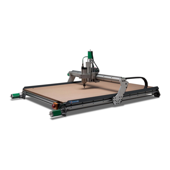
- Page 1 GALAXY SERIES CNC ROUTERS Quick Start Guide www.probotix.com 844-472-9262...
-
Page 2: How To Get Help
HOW TO GET HELP Online Support http://www.probotix.com/wiki/ http://www.probotix.com/forum/ Telephone Support 844-472-9262... - Page 3 MACHINE FOOTPRINTS...
- Page 4 BUILDING A TABLE - COMET 3/4” MDF or Plywood, 34” x 36” 3/4” MDF or Plywood, 24.5” x 34.5” 2pcs 1x4 Pine, 34” Long 2pcs 1x4 Pine, 34.5” Long 2pcs 1x4 Pine, 25.5” Long 2pcs 1x4 Pine, 33” Long 4pcs 4x4 Pine, 27.25” Long...
- Page 5 BUILDING A TABLE - ASTEROID 3/4” MDF or Plywood, 46” x 36” 3/4” MDF or Plywood, 37.5” x 34.5” 2pcs 1x4 Pine, 46” Long 2pcs 1x4 Pine, 34.5” Long 2pcs 1x4 Pine, 37.5” Long 2pcs 1x4 Pine, 33” Long 4pcs 4x4 Pine, 27.25” Long 4pcs 3.5”...
- Page 6 BUILDING A TABLE - METEOR 3/4” MDF or Plywood, 34” x 64.5” 3/4” MDF or Plywood, 25.5” x 63” 2pcs 1x4 Pine, 34” Long 2pcs 1x4 Pine, 63” Long 2pcs 1x4 Pine, 25.5” Long 2pcs 1x4 Pine, 61.5” Long 4pcs 4x4 Pine, 27.25” Long 4pcs 3.5”...
- Page 7 BUILDING A TABLE - NEBULA 3/4” MDF or Plywood, 46” x 64.5” 3/4” MDF or Plywood, 37.5” x 63” 2pcs 1x4 Pine, 46” Long 2pcs 1x4 Pine, 63” Long 2pcs 1x4 Pine, 37.5” Long 2pcs 1x4 Pine, 61.5” Long 4pcs 4x4 Pine, 27.25” Long 4pcs 3.5”...
- Page 8 CONNECTION DIAGRAM (ROUTER) UNITY CONTROLLER COMPUTER 110VAC POWER MACHINE HARNESS PARALLEL CABLE USB CABLE KEYBOARD, MOUSE, MONITOR, JOG PENDANT...
- Page 9 CONNECTION DIAGRAM (VFD SPINDLE) UNITY CONTROLLER COMPUTER 110VAC POWER MACHINE HARNESS PARALLEL CABLE USB CABLE KEYBOARD, MOUSE, MONITOR, JOG PENDANT VFD CONTROL CABLE 220VAC...
- Page 10 UNITY CONTROLLER PORTS A: AC INPUT - Primary power input for power supply. B: AC INPUT - Power input here is switched by relay to the (C) ROUTER output. C: ROUTER - Connect to the green power cable from the machine harness. On-screen spindle controls, as well as M3/M5 g-codes will control this output.
- Page 11 VFD WIRING DETAIL JUMPER SET TO “VI” 220VAC@20AMP SPINDLE 1) 24V PWR (RED) 2) GND (BLK) U,V,W 3) 0-10V (WHT) TO SPEED CONTROL BOARD EARTH GND TO MACHINE FRAME NOTICE: Internal wiring of Chinese spindles is not consistent. If spindle spins in reverse, swap U & V. You MUST verify visually or physically the proper rotation of the spindle to ensure the machine cuts properly!
- Page 12 VFD WIRING DETAIL (SUNFAR E300) 220VAC@20AMP SPINDLE 1) 24V PWR (RED) 2) GND (BLK) U,V,W 3) 0-10V (WHT) TO SPEED CONTROL BOARD EARTH GND TO MACHINE FRAME NOTICE: Internal wiring of Chinese spindles is not consistent. If spindle spins in reverse, swap U & V. You MUST verify visually or physically the proper rotation of the spindle to ensure the machine cuts properly!
- Page 13 VFD WIRING DETAIL (SUNFAR E500) 220VAC@20AMP SPINDLE 1) 24V PWR (RED) 2) GND (BLK) U,V,W 3) 0-10V (WHT) TO SPEED CONTROL BOARD EARTH GND TO MACHINE FRAME NOTICE: Internal wiring of Chinese spindles is not consistent. If spindle spins in reverse, swap U & V. You MUST verify visually or physically the proper rotation of the spindle to ensure the machine cuts properly!
-
Page 14: Limit Switches
LIMIT SWITCHES The Y1 and Y2 limit switches have been removed to protect them during transport. Reinstall them as seen above before running the machine. -
Page 15: Getting Started
GETTING STARTED Simple Start Up Procedure: Start computer Ÿ Launch LinuxCNC from icon on desktop Ÿ Turn power on Unity Controller Ÿ Verify red E-Stop indicator follows physical e-stop Ÿ Click orange Machine Power button Ÿ Click the Home All button Ÿ... - Page 16 CAM SOFTWARE You can use any CAM software to generate g-code for LinuxCNC. Most CAM software programs will have appropriate post processors named either LinuxCNC or EMC2. You can use generic g-code post processors as well. We also have post processors on our wiki specifically for our machines.
- Page 17 The most efficient way to manage this is to create seperate post processor for each tolerance level you want to use. Do not confuse G64 Path Optimization with the G54 Coordinate System More information about this and other topics can be found on the wiki: http://www.probotix.com/wiki/...
-
Page 18: Maintenance
MAINTENANCE Daily Use: Put a couple of drops of 3-in-1 oil on each of the six linear rails before homing the machine each day. This will allow a tiny amount of oil to be sucked up into the bearing housings before cutting any parts. Use the included linear motion grease on the leadscrews. - Page 19 LINUXCNC KEYBOARD SHORTCUTS ESCAPE E-STOP TOGGLE E-STOP TOGGLE MACHINE POWER MANUAL MODE AUTO MODE MDI MODE RESET INTERPRETER TOGGLE MIST TOGGLE FLOOD TOGGLE SPINDLE FORWARD TOGGLE SPINDLE REVERSE DECREASE SPINDLE SPEED INCREASE SPINDLE SPEED SELECT X-AXIS SELECT Y-AXIS SELECT Z-AXIS LEFT/RIGHT ARROW JOG X-AXIS UP/DOWN ARROW...
- Page 20 G-CODE QUICK REFERENCE Motion Rapid motion Coordinated motion ("Straight feed") G2, G3 I J K or R Coordinated helical motion ("Arc feed") CW or CCW G38.2 Straight Probe Cancel motion mode R L P Drilling Cycle G82…G89 R L P Q Other canned cycles Spindle-synchronized motion G33.1...
- Page 21 This position is expressed as: X3.0 Y2.0 Z1.0 ORIGIN...
- Page 22 31-5000 - G code user parameters. These parameters are global in the G code file, and available for general use. Volatile. 5061-5069 - Coordinates of a "G38.2" Probe result of X, Y, Z, A, B, C, U, V & W. Volatile. 5070 - "G38"...
- Page 23 ALUMINUM STAND ASSEMBLY Aluminum Stand Assembly Extrusion Lengths (mm) COMET ASTEROID METEOR NEBULA 4x Legs (6060) Front/Back (3060) Top Sides (3060) 1528 1528 Bottom Sides (3060) 1414 1414 All rails are mounted inside the legs flush to the outside, except for the C rails, which mount to the outside.
- Page 24 ALUMINUM STAND MULTI-MOUNTS...
- Page 25 KVM ARM If you also have the KVM arm, you can mount it to the frame as seen above.
Need help?
Do you have a question about the COMET and is the answer not in the manual?
Questions and answers