Advertisement
Quick Links
PRECAUTIONS AGAINST ELECTRIC SHOCK HAZARD.
Disconnect mains supply before removing cover.
Installation & maintenance must be carried out by suitably qualified
personnel and in accordance with current IEE wiring regulations.
Do not mount to unearthed metal or metalised surfaces.
Fixed wiring installation must be employed. A class 'A' switch, (having
contact separation of at least 3mm in all poles) must be incorporated in the fixed wiring as a
means of disconnecting the supply. Use a fuse rated at 3 amps to protect the system.
TECHNICAL DATA.
Function:
Control of room temperature by electrical switching of control circuit.
Construction:
Electro Mechanical Switch.
Supply Voltage:
230V~, 50Hz.
Switch Rating:
15(2.5)A
Enclosure Insulation:
Class II, (double insulated).
Enclosure Protection:
IP20.
Pollution Situation:
Normal.
Ambient Temperature:
0 to 50
Ambient Humidity:
5 to 95% Relative Humidity.
Operating Range:
6 to 30
Switching Differential:
1.3
Installation Details:
See wiring diagram below and installation instructions overleaf.
230V~
IN ACCORDANCE WITH OUR POLICY OF CONTINUAL PRODUCT IMPROVEMENT, WE RESERVE THE RIGHT TO AMEND THE
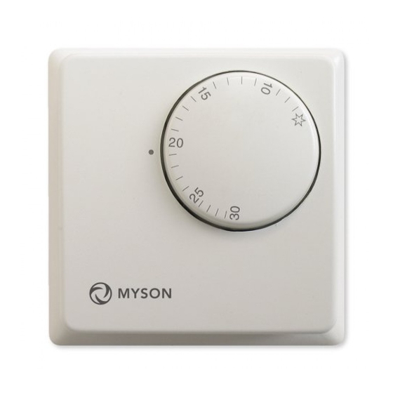
MYSON MRT1: ROOM TEMPERATURE THERMOSTAT.
INSTALLATION INSTRUCTION.
o
C.
o
C.
o
C.
N
L
CIRCUIT WIRING DIAGRAM.
MYSON CONTROLS
MYSON LTD, EASTERN AVENUE,
TEAM VALLEY, GATESHEAD,
TYNE & WEAR, NE11 0PG
SALES OFFICE No.: 0845 402 3434
SPECIFICATION OF THESE PRODUCTS WITHOUT PRIOR NOTIFICATION.
4 3
1
HEATING
LOAD
SC1959: Revision 2.
Advertisement

Related Manuals for Myson MRT1


Summary of Contents for Myson MRT1
- Page 1 MYSON MRT1: ROOM TEMPERATURE THERMOSTAT. INSTALLATION INSTRUCTION. PRECAUTIONS AGAINST ELECTRIC SHOCK HAZARD. Disconnect mains supply before removing cover. Installation & maintenance must be carried out by suitably qualified personnel and in accordance with current IEE wiring regulations. Do not mount to unearthed metal or metalised surfaces.
- Page 2 INSTALLATION INSTRUCTION. POSITIONING OF THERMOSTAT. COVER REMOVAL. 3: Rotate cover free of the thermostat. 1: Insert blade of screwdriver into the clip slot on the side of the thermostat. 1: Locate the thermostat at a height between 1 and1.5 metres from the floor. 2: Do not locate in a position directly exposed to heat from the radiator, sunlight, or other heat 2: Lever screwdriver upwards to prise sources...
Need help?
Do you have a question about the MRT1 and is the answer not in the manual?
Questions and answers