Advertisement
Quick Links
JY997D16301E
Side
JAPANESE
A
Side
ENGLISH
B
FX
-4HSX-ADP
3U
INSTALLATION MANUAL
Manual Number
JY997D16301
Revision
E
Date
October 2017
This manual describes the part names, dimensions, mounting, and specifications
of the product. Before use, read this manual and manuals of relevant products
fully to acquire proficiency in handling and operating the product. Make sure to
learn all the product information, safety information, and precautions.
And, store this manual in a safe place so that you can take it out and read it
whenever necessary. Always forward it to the end user.
Registration
The company name and the product name to be described in this manual are the
registered trademarks or trademarks of each company.
Effective October 2017
Specifications are subject to change without notice.
©
2005 Mitsubishi Electric Corporation
Safety Precaution
(Read these precautions before use.)
This manual classify the safety precautions into two categories:
and
.
Indicates that incorrect handling may cause hazardous
conditions, resulting in death or severe injury.
Indicates that incorrect handling may cause hazardous
conditions, resulting in medium or slight personal injury or
physical damage.
Depending on circumstances, procedures indicated by
may also be
linked to serious results.
In any case, it is important to follow the directions for usage.
Associated Manuals
Manual name
Manual No.
Description
FX
Series
JY997D16501
3U
E x p l a i n s F X
3 U
S e r i e s P L C
User's Manual
MODEL
specification details for I/O, wiring,
installation, and maintenance.
- Hardware Edition
CODE: 09R516
FX
3S
/FX
3G
/FX
3GC
/FX
3U
/
FX
3UC
Series
JY997D16601
Describes PLC programming for
Programming Manual
MODEL
basic/applied instructions and
devices.
-
B a s i c
&
A p p l i e d
CODE: 09R517
Instruction Edition
How to obtain manuals
For the necessary product manuals or documents, consult with the Mitsubishi
Electric dealer from where you purchase your product.
Applicable Standard
FX
-4HSX-ADP complies with EC directive (EMC Directive) and UL standards
3U
(UL, cUL). Further information can be found in the following manual.
→ FX
Series Hardware Manual (Manual No. JY997D50301)
3U
Attention
This product is designed for use in industrial applications.
Side
B
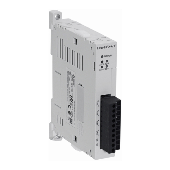
1. Outline
FX
-4HSX-ADP high-speed input special adapter (hereinafter called high-speed input
3U
special adapter) is a special adapter dedicated to FX
Series PLC. It retrieves pulse
3U
signals from a rotary encoder of which the output type is a differential line driver to a
high-speed counter or SPD instruction (FNC 56).
Up to two units of this high-speed special adapter can be connected to the main unit
per system. For details on system configuration, refer to the following manual.
→ FX
Series User's Manual - Hardware Edition
3U
1.1 Incorporated Items
Check if the following product and items are included in the package:
Product
FX
-4HSX-ADP high-speed input special adapter
3U
Accessories
Installation manual (This manual)
1.2 Input Allocation and Usable High-Speed Counter Number
When the power is turned on, input numbers of the high-speed input special adapters
are allocated as shown in the table below in the order of unit position to the main unit.
See the table below for usable device number of associated high-speed counter. For
details on high-speed counters, refer to the following manual.
→ FX
3U
Series User's Manual - Hardware Edition
Second unit
High-
High-
High-
Analog
Analog
Analog
speed
speed
speed
special
special
special
input
output
output
function
function
function
special
special
special
adapter
adapter
adapter
adapter
adapter
adapter
*1 An expansion board is required to use any special adapters other than high-
speed I/O special adapters. For system configuration, refer to the following
manual.
→ FX
3U
Series User's Manual - Hardware Edition
Input number
Associated high-speed counters
C235, C236, C237, C241, C242
First unit X000 to X002, X006
*3
C245
, C246, C247, C249, C251, C252, C254
Second
C 2 38 , C 2 39 , C 2 40 , C 2 43 , C 2 45 (O P ), C 2 48 ,
X003 to X005, X007
unit
C248(OP), C250, C253, C253(OP), C255
*2 Use the terminal of the main unit for reset input if the second high-speed input
special adapter is not connected.
*3 Use the terminal of the main unit for start input and reset input if the second high-
speed input special adapter is not connected.
Caution
When connecting a high-speed input special adapter, same input numbers are
allocated to the main unit and this special adapter. Must use either one of the
input terminals. If both input terminals are used, assumed action may not be
executed because inputs of the high-speed input special adapter and main unit
are operated in an OR relationship to each other.
• Do not use (wire) the input terminal in main unit corresponding to the input
number used in the high-speed input special adapter.
• Do not use (wire) the input terminal in high-speed input special adapter
corresponding to the input number used in the main unit.
1.3 External Dimensions, Part Names, and Terminal Layout
[4]
[5]
[6]
[3]
[2]
[1]
7 (0.28")
74 (2.92")
First unit
Terminal layout of [6]
Special adapter
connector cover [2]
or [5] is removed
High-
Name
speed
Main unit
input
special
X0/3+
adapter
X0/3-
*1
Expansion board
X1/4+
Input LED [7]
X1/4-
Input number
X2/5+
Name
First
Second
unit
unit
X2/5-
X0/3
X000
X003
X6/7+
X1/4
X001
X004
X6/7-
X2/5
X002
X005
SG
*2
, C244, C244(OP),
X6/7
X006
X007
SG
[1] DIN rail mounting groove (DIN rail: DIN46277)
[2] High-speed I/O special adapter connector cover:
Remove this cover for connecting high-speed I/O special adapter on the left side.
[3] Name plate
[4] Special adapter slide lock:
Used to connect special adapter on left side of this special adapter.
[5] Special adapter connector cover:
Remove this cover for connecting special adapter on the left side.
[6] Terminal block for inputs (European type):
Connects output signals of differential line driver type.
[7] Input LED (red):
Lit when input turns ON (if input turns ON and OFF alternately at high speed, the
LED flickers fast).
[8] POWER LED (green):
Lit while power is properly supplied from main unit.
[9] Direct mounting hole:2 holes of φ4.5 (0.18") (mounting screw: M4 screw)
[10] Special adapter fixing hook
[11] DIN rail mounting hook
[12] Special adapter connector:
Used to connect the communication special adapter or analog special adapter to
this adapter on left side.
[13] High-speed I/O special adapter connector:
Used to connect the high-speed I/O special adapter to this adapter on left side.
2. Installation
The product can be mounted on DIN rail (DIN46227) or mounted directly using
[9]
[10]
screws.
For installation/uninstallation and safety precautions, refer to the following
manual:
FX -4HSX-ADP
[8]
3U
[7]
POWER
X0/3 X2/5
INSTALLATION
X1/4
X6/7
PRECAUTIONS
• Make sure to cut off all phases of the power supply externally before
attempting installation or wiring work.
Failure to do so may cause electric shock or damage to the product.
INSTALLATION
PRECAUTIONS
[11]
• Use the product within the generic environment specifications described in
PLC main unit manual (Hardware Edition).
[9]
Never use the product in areas with excessive dust, oily smoke, conductive
15.1 (0.60")
dusts, corrosive gas (salt air, Cl
15.5 (0.62")
17.6 (0.70")
or impacts, or expose it to high temperature, condensation, or rain and wind.
If the product is used in such conditions, electric shock, fire, malfunctions,
deterioration or damage may occur.
• When drilling screw holes or wiring, make sure that cutting and wiring debris
Input number
do not enter the ventilation slits.
[12]
Failure to do so may cause fire, equipment failures or malfunctions.
First
Second
unit
unit
• Do not touch the conductive parts of the product directly.
X000+
X003+
Doing so may cause device failures or malfunctions.
• Connect the special adapter securely to their designated connectors.
X000-
X003-
Loose connections may cause malfunctions.
X001+
X004+
[13]
X001-
X004-
2.1 Connection to the FX
X002+
X005+
• Refer to the procedure 2) for configuring a new system.
X002-
X005-
• Refer to the procedure 1) for adding product to an existing system.
X006+
X007+
Procedure
1) Turn off the power.
X006-
X007-
Disconnect all the cables connected to the PLC main unit and special adapter.
SG
SG
Dismount the main unit and special adapter mounted on DIN rail or mounted
SG
SG
directly using screws.
2) Install an expansion board to the main unit.
Unit
: mm (inches)
For installation of expansion board, refer to the following manual:
Weight: Approx. 80g (0.18 lbs)
3) Remove the high-speed I/O special adapter
connector cover (Right fig. A) and the special
adapter connector cover (Right fig. B) on the
main unit.
In case of connecting this product to a high-
speed I/O special adapter as an addition,
please replace the 'main unit' in the above
description with a 'special adapter' and
perform the procedure as indicated. (Please
replace the following procedures similarly.)
4) Slide the special adapter slide lock (Right
fig.C) of the main unit.
5) Connect the high-
speed I/O special
adapter (Right fig.D)
to the main unit as
shown on the right.
6) Slide back the
special adapter
slide lock (Right
fig.C) of the main
unit to fix the high-
speed I/O special
adapter (Right
fig.C).
Connection precautions
• Install the expansion board to be used before connecting a special adapter.
• Install an expansion board when using a special adapter other than a high-
speed I/O special adapter in combination with a high-speed I/O special
adapter.
• Connect all the high-speed I/O special adapters before connecting other
special adapters when they are used in combination.
Do not connect a high-speed I/O special adapter on the left side of any
special adapters other than other high-speed I/O special adapters.
→ FX
Series User's Manual - Hardware Edition
3U
, H
S, SO
or NO
), flammable gas, vibration
2
2
2
2
Series PLC
3U
→ FX
Series User's Manual - Hardware Edition
3U
4)
3)
C
4)
4)
B
A
C
C
D
6)
5)
6)
6)
5)
5)
C
Advertisement

Related Manuals for Mitsubishi Electric FX3U-4HSX-ADP


Summary of Contents for Mitsubishi Electric FX3U-4HSX-ADP
- Page 1 Specifications are subject to change without notice. • Connect the special adapter securely to their designated connectors. X0/3- X000- X003- © 2005 Mitsubishi Electric Corporation Loose connections may cause malfunctions. Expansion board X1/4+ X001+ X004+ Input LED [7] [13]...
- Page 2 (or CRIMPFOX 6T-F 4.4 Performance Specification This manual confers no industrial property rights or any rights of any other kind, nor does it confer any patent licenses. Mitsubishi Electric Corporation cannot be *1 Old model name: CRIMPFOX ZA 3 Item Specification Note: This symbol mark is for China only.
- Page 3 (or CRIMPFOX 6T-F This manual confers no industrial property rights or any rights of any other kind, 4.4 Performance Specification nor does it confer any patent licenses. Mitsubishi Electric Corporation cannot be *1 Old model name: CRIMPFOX ZA 3 Item Specification Note: This symbol mark is for China only.
Need help?
Do you have a question about the FX3U-4HSX-ADP and is the answer not in the manual?
Questions and answers