Table of Contents
Advertisement
Quick Links
Advertisement
Table of Contents

Related Manuals for Toshiba DP1200


Summary of Contents for Toshiba DP1200
- Page 1 DIGITAL PLAIN PAPER COPIER DP1200/1500 File No. 31100024...
- Page 2 Copyright 2001 TOSHIBA TEC CORPORATION...
- Page 3 DP1200/1500 CAUTION This product is a class 1 laser product that complies with 21CFR 1040.10 and 1040.11 of the CDRH stand- ard and IEC825. This means that this machine does not produce hazardous laser radiation. The use of controls, adjustments or performance of procedures other than those specified herein may result in haz- ardous radiation exposure.
- Page 4 DP1200/1500 Caution At the production line, the output power of the scanner unit is adjusted to 0.57 This product contains a low power laser MILLI-WATT PLUS 20 PCTS and is device. To ensure continued safety do not maintained constant by the operation of remove any cover or attempt to gain access the Automatic Power Control (APC).
-
Page 5: Table Of Contents
LOADING COPY PAPER ....................5-3 POWER TO COPIER ....................... 5-4 CONNECTING THE INTERFACE CABLE (DP1200 Only) ..........5-4 6. INSTALLING THE PRINTER DRIVER SOFTWARE (DP1200 Only) ......6-1 Description of the printer driver ..................6-1 Checking the hardware and software requirements ............6-1 Installing the printer driver .................... - Page 6 7. OPERATIONAL DESCRIPTIONS ................7-1 Outline of operation ......................7-1 Scanner section ........................ 7-2 Laser unit ......................... 7-2 Fuser section ........................7-3 Paper feed section and paper transport section ............... 7-4 Printing process ....................... 7-7 8. DISASSEMBLY AND ASSEMBLY ................8-1 High voltage section ......................
-
Page 7: General
DP1200/1500 [1] GENERAL 1. DP1200/1500 major functions Item GDI without GDI with PCL6 with SB/MB 2 tray SPF (ADF) SOPM Model DP1200 12CPM DP1500 15CPM Descriptions of items CPM: Copy speed (Copies Per Minute) SB/MB: SB = Manual feed single bypass, MB = Manual feed multi bypass 2 tray: Second cassette unit. -
Page 8: Specifications
DP1500: Approx. 19kg (TBD) B. Operation specification Section Item Details Spec. Paper feed DP1200, DP1500: 1 tray (250 sheets) + multi bypass (50 sheets) system Paper size A4, B5, A5 (Landscape) Paper weight 56 – 80g/m Tray paper feed section... - Page 9 Power source Frequency Common use for 50 and 60Hz Max. DP1200/DP1500: 1000W Electrical section Average (operating) * DP1500: 310Wh/H, DP1200: 270Wh/H Power consumption Stand-by mode DP1200/DP1500: 70Wh/H (initial condition) * Pre-heat mode * DP1200/DP1500: 40Wh/H Auto power shut-off mode * DP1200/DP1500: 18Wh/H *1) May fluctuate due to environmental conditions and the input voltage.
- Page 10 Copy speed First copy time 10.0 sec (Pre-heat mode: 16 sec. or below / Auto Manual paper feed power-shut-off mode: 23 sec. or below) Same size DP1200: 12 DP1500: 15 AB system: A4 Copy speed (CPM) Enlargement DP1200: 12 DP1500: 15...
-
Page 11: Consumable Parts
DP1200/1500 [3] CONSUMABLE PARTS 1. Supply system table Name Model name Life Package unit Remark Toner Cartridge PS-ZT1200 6.5K Life based on 6% coverage of A4 original. Developer D-1200 (6%) Drum Kit OD-1200 2. Environmental 3. Production control number (lot No.) -
Page 12: Td Cartridge Replacement
DP1200/1500 4. TD cartridge replacement Division 1) Open the front and side cabinets of the copier. Ex production 2) Keep holding Toner lover, and Option 3) Carefully pull out Toner unit from the copier. Same pack Production control label attachment position... -
Page 13: External Views And Internal Structures
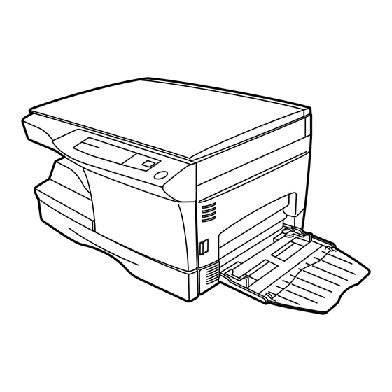
DP1200/1500 [4] EXTERNAL VIEWS AND INTERNAL STRUCTURES 1. Appearance (10) (11) (12) (13) Original table Original cover Side cover Operation panel Front cover Paper tray Side cover open button Paper guides Handle (10) Paper output tray (11) Paper output tray extension... -
Page 14: Operational Panel
DP1200/1500 3. Operational panel (3) (4) (5) (10) (11) (12) (13) (16) (17) (18) (19) (14) (15) Inch system Exposure mode selector key Light and dark keys and ∗1 Alarm indicators and indicators exposure indicators Copy ratio selector key and... -
Page 15: Motors And Solenoids
DP1200/1500 4. Motors and solenoids Part name Control signal Function,operation Main motor Drives the copier. Mirror motor MRMT Drives the optical mirror base (scanner unit). Toner motor Supplies toner. Cooling fan motor Cools the optical section. Resist roller solenoid Resist roller rotation control solenoid... -
Page 16: Sensors And Switches
DP1200/1500 5. Sensors and switches Name Signal Type Function Output Mirror home position Mirror (scanner unit) MHPS Transmission sensor “H” at home position sensor home position detection POD sensor Transmissions sensor Paper exitdetection “H” at paper pass Paper transport PPD2 sensor... -
Page 17: Pwb Unit
DP1200/1500 6. PWB unit Name Function Exposure lamp invertor PWB Exposure lamp (Xenon lamp) control Main PWB (MCU) Copier control Operation PWB Operation input/display Power PWB AC power input, DC voltage control, High voltage control CCD sensor PWB For image scanning... -
Page 18: Cross Sectional View
DP1200/1500 7. Cross sectional view (10) (11) (12) (13) (14) (15) Part name Function and operation Illuminates the original with the copy lamp and passes the reflected light to the lens unit Scanner unit (CCD). Exposure lamp Exposure lamp (Xenon lamp) Illuminates original Lens unit Scans the original image with the lens and the CCD. -
Page 19: A Word On Copier Installation
2. CHECKING PACKED COMPONENTS AND ACCESSORIES Open the carton and check if the following components and ac- cessories are included. Power cord Operation manual (CD-ROM : DP1200 Only) exposed to direct sunlight Copier Drum cartridge (installed in copier) 3. UNPACKING... -
Page 20: Developer Unit Installation
DP1200/1500 2) Use a coin (or suitable object) to remove the screw. 8) Remove Upper developer unit. Store the screw in the paper tray because it will be used if the copier has to be moved. 3) Open the bypass tray and then open the side cover whilst 9) Shake the aluminum bag to stir developer pressing the side cover open button. -
Page 21: Toner Cartridge Installation
DP1200/1500 13) Insert Developer unit carefully into the copier. Note: Do not hold and carry the shutter. Otherwise the shut- Note: Quick insertion may result in splash of developer. Be ter may drop and Toner unit may drop. sure to insert carefully. -
Page 22: Power To Copier
DP1200/1500 9. CONNECTING THE INTERFACE CABLE (DP1200 Only) For specifications of the parallel interface, see page 6-3. 1) Check that the power switches of both the printer and the computer are in the OFF position. 2) Plug the parallel interface cable into the printer interface... -
Page 23: Installing The Printer Driver Software (Dp1200 Only)
A. Windows 95/Windows NT 4.0: INSTALLING THE PRINTER DRIVER 1) Load paper into the paper tray of the printer. SOFTWARE (DP1200 Only) 2) Turn on the printer. 1. Description of the printer driver The printer driver is the software program which runs the 3) Turn on your computer and start Windows. - Page 24 Next button. To select a different folder, select Browse and type in the new path 7) Windows driver file search will find the device TOSHIBA and folder name. Click OK and say YES to create the e-STUDIO Series.
-
Page 25: Printer Driver Group
GND (DATA4 RET) 4. Printer driver group DATA5 GND (DATA5 RET) When the printer driver is installed, the TOSHIBA e-STUDIO Series DATA6 GND (DATA6 RET) printer driver group will be created. This group allows the fol- lowing functions to be executed. -
Page 26: Operational Descriptions
DP1200/1500 [7] OPERATIONAL DESCRIPTIONS 1. Outline of operation The outline of operation is described referring to the basic configuration. (Basic configuration) Scanner section Operation section MCU (Main control/image process section) LSU (Laser unit) Laser diode, Polygon mirror lens Laser beam... -
Page 27: Scanner Section
DP1200/1500 2. Scanner section Sub scanning direction Sensor scanning area A. How to scan documents Main The scanner has sensors that are arranged in a line. These sensors scan a scanning direction certain area of a document at a time and deliver outputs sequentially. When the line is finished, the next line is scanned, and this procedure is repeated. -
Page 28: Fuser Section
DP1200/1500 4. Fuser section Component Function Semiconductor laser Generates laser beams. Converges laser beams in Collimator lens parallel. Polygon mirror, Reflects laser beams at a polygon motor constant rpm. BD (Mirror, lens, Detects start timing of laser PWB) scanning. Converges laser beams at a spot on the drum. -
Page 29: Paper Feed Section And Paper Transport Section
DP1200/1500 2. The surface temperature of the upper heat roller is set to 165˚C ∼ (3) Thermal control 1. The heater lamp, thermistor, main PWB, DC power supply PWB, 190˚C. The surface temperature during the power save mode is set and triac within the power supply unit are used to control the to 100˚C. - Page 30 DP1200/1500 (1) Cassette paper feed operation 5) At this time, the paper is fed past the paper entry detection switch 1) The figure below shows the positions of the pick-up roller, the paper (PPD1), and detected by it. After about 0.15 sec from detection of...
- Page 31 DP1200/1500 (2) Manual multi paper feed operation 3) When pawl C of the manual paper feed clutch sleeve is hung on the 1) Before paper feed operation, the manual paper feed solenoid manual feed latch, the manual feed stopper falls and the manual (MPFS) is turned OFF as shown in the figure below.
-
Page 32: Printing Process
DP1200/1500 (3) Conditions of occurrence of paper misfeed a. When the power is turned on: PPD or POD is ON when the power is turned on. b. Copy operation 1) PPD1 does not turn off within 4 sec a. PPD1 jam after turning on the resist roller. - Page 33 DP1200/1500 Semiconductor laser (2) Outline of print process This printer is a non-impact printer that uses a semiconductor laser and electrostatic print process. This printer uses an OPC (Organic Photo Conductor) for its photoconductive material. First, voltage from the main corona unit charges the drum sur- face and a latent image is formed on the drum surface using a laser beam.
- Page 34 DP1200/1500 Step-7: Optical discharge (Semiconductor laser) Non-image area Before the drum rotation is stopped, the semiconductor laser is -600 radiated onto the drum to reduce the electrical resistance in the OPC layer and elimate residual charge, providing a uniform state to the drum surface for the next page to be printed.
- Page 35 DP1200/1500 Start 1) Because the grid potential is at a low level, the drum poten- tial is at about –400V. (Carrier may not be attracted though the carrier is pulled towards the drum by the electrostatic force of –400V. 2) Developing bias ( –400V) is applied when the photoconduc- tor potential is switched from LOW to HIGH.
-
Page 36: Disassembly And Assembly
DP1200/1500 2) Remove the drum fixing plate and the photoconductor drum. [8] DISASSEMBLY AND ASSEMBLY (Note) Dispose the drum fixing plate which was removed. Before disassembly, be sure to disconnect the power cord for safety. The disassembly and assembly procedures are described for the fol- lowing sections: 1. - Page 37 DP1200/1500 5) Remove the cleaning blade. Attach the mocket with slightly pressing section A of the cleaning blade. Note: Dispose the cleaning blade which was removed. Do not touch the tip of the cleaning blade. Do not put the mocket under the cleaning blade.
- Page 38 DP1200/1500 12) Attach the detection gear. (2) Push up the lock pawls (2 positions) of the side cover, and remove Note: the transfer charger. • The detection gear is not installed to the drum cartridge packed with the main body. Add a new one.
-
Page 39: Operation Panel Section
DP1200/1500 (2) Set the charger cleaner to the transfer unit, and move it reciprocal- 2. Operation panel section ly a few times in the arrow direction shown in the figure below. A. List Part name Ref. Operation panel unit Operation PWB B. -
Page 40: Optical Section
DP1200/1500 (2) Remove the screws (2pcs.), and remove the copy lamp unit from C. Assembly procedure the mirror base drive wire. For assembly, reverse the disassembly procedure 3. Optical section A. List Part name Ref. Copy lamp unit Copy lamp Lens unit B. -
Page 41: Fusing Section
DP1200/1500 (5) Remove the screws (2 pcs.), the harness, and the optical unit. 4. Fusing section A. List Part name Ref. Thermistor PPD2 sensor Heater lamp Pressure roller Heat roller B. Disassembly procedure (1) Remove the connectors (3 pcs.) of the rear cabinet. - Page 42 DP1200/1500 (4) Remove the screw and remove the U-turn guide. (7) Remove the plate spring on the right and remove the heater lamp. Pressure roller section disassembly Hearter lamp Remove the three screws, remove the fusing cover lower on the right side, and open the heat roller section.
- Page 43 DP1200/1500 (10) Remove the pressure release levers on the right and the left (6) Remove the C-ring and the fusing bearing, and remove the heat sides. roller. Heat roller (7) Remove the parts from the heat roller. Note: Apply grease to the sections specified with (11) Remove the pressure roller, the pressure bearing, and the spring.
-
Page 44: Tray Paper Feed/Transport Section
DP1200/1500 (3) Remove two screws and remove the toner motor. 5. Tray paper feed/transport section A. List Part name Ref. PPD1 sensor PWB LSU unit Intermediate frame unit Paper feed roller B. Disassembly procedure (1) Remove six connectors and screws of the main PWB, and lift the optical unit and the main PWB to remove. - Page 45 DP1200/1500 (5) Remove the pulleys on the both sides and remove the paper exit (7) Release the belt pulley lock and remove the belt pulley bearing. roller. (8) Remove the paper exit roller. (6) Pull out the paper exit roller knob and remove the belt.
- Page 46 DP1200/1500 (9) Remove the harness guide. (11) Remove the parts as shown below, and remove the pressure release solenoid and the paper feed solenoid. (10) Remove five screws and remove the main drive plate and the belt. (12) Remove six screws and remove the LSU unit.
- Page 47 DP1200/1500 (13) Remove two screws and remove the fusing connector. (17) Remove three screws and remove the TC front paper guide. (14) Remove five screws and the connector, and lift the intermediate frame unit to remove. (18) Remove the screw and the connector, and remove the PPD1 sensor PWB.
-
Page 48: Manual Paper Feed Section
DP1200/1500 (19) Remove two E-rings and remove the paper feed roller. 6. Manual paper feed section (20) Remove three E-rings and remove the clutch unit. A. List Part name Ref. Back Manual transport roller Cassette detection switch PPD1 sensor PWB... - Page 49 DP1200/1500 (2) Remove the screw and remove the side door detection unit. (4) Remove the PPD1 sensor PWB. Back Wire treatment (3) Remove three screws and remove the single manual feed upper frame. Wire treatment (5) Remove the E-ring and remove the manual paper feed transport roller.
- Page 50 DP1200/1500 (6) Remove the cassette detection switch. Multi unit (1) Remove the screw and remove the multi upper cover. Wire treatment (2) Remove the screw and remove the side door detection unit. (7) Remove the multi cover. Orange Multi cover...
- Page 51 DP1200/1500 (3) Remove three screws and remove the multi paper feed upper (5) Remove three E-rings and remove the manual paper feed roller. frame. (4) Remove two screws and remove the multi feed bracket unit from the multi paper feed upper frame.
-
Page 52: Rear Frame Section
DP1200/1500 (7) Cut the binding band and remove the multi paper feed solenoid. 7. Rear frame section A. List Part name Ref. Mirror motor Main motor Exhaust fan motor B. Disassembly procedure (1) Remove three screws and remove the rear cabinet. -
Page 53: Power Section
DP1200/1500 (3) Remove two screws and one harness, and remove the main 8. Power section motor. A. List Part name Ref. Power PWB B. Disassembly procedure (1) Remove two screws and one connector, and remove the power PWB. (4) Remove two screws and one connector, and remove the exhaust C. -
Page 54: Adjustments
DP1200/1500 d. Adjustment procedure [9] ADJUSTMENTS 1) Remove the right cabinet (manual paper feed unit), the docu- 1. Optical section ment reference plate. A. Image distortion adjustment 2) Remove the document glass. There are following two types of image distortion. - Page 55 DP1200/1500 7) Manually turn the copy lamp unit/No.2/3 mirror unit drive gear to bring No.2/3 mirror unit into contact with the positioning plate, and perform the procedure of step 4). Repeat procedures of steps 4) to 7) until the parallelism of No.2/3 mirror unit is properly set.
- Page 56 DP1200/1500 10) Check the horizontal image distortion. (2) Vertical image distortion adjustment If LL = LR, there is no horizontal distortion a. Summary In this adjustment, the left and right balance is adjusted by changing LL and LR: Distance between the copy the left and right balance of the No.
- Page 57 DP1200/1500 3) If the right-left distortion balance is improper, loosen the fixing (1) Outline screw of No.2/3 mirror unit rail to change and adjust the right-left The main scanning (front/rear) direction magnification ratio adjust- balance of No.2/3 mirror unit rail.
- Page 58 DP1200/1500 4) Measure the length of the copied scale image. 5) Calculate the main scanning direction magnification ratio. Main scanning direction magnification ratio Copy image dimensions × 100 (%) Original dimension (When a 100mm scale is used as the original.)
- Page 59 DP1200/1500 Original (Scale) HARDDENCD STAINLESS JAPAN 1/2mm Shizuoka Paper feed HARDDENCD direction STAINLESS JAPAN 1/2mm Shizuoka Reference Comparison point Copy 6) Check that the actual copy magnification ratio is within the D. Image position adjustment specified range. (100 ± 1.0%).
- Page 60 DP1200/1500 (1) Lead edge adjustment 3) Make a copy and measure the void amount of image rear edge. 1) Set a scale to the center of the paper lead edge guide as shown below, and cover it with B4 or 8 1/2″ × 14″ paper.
-
Page 61: User Program
Check that the voltage at the high voltage section and the develop- ing bias voltage are in the specified range. C. Necessary tool for copy density adjustment TOSHIBA TEST CHART No.15-1. B4 (14 8 1/2 ) white paper (2) Perform the adjustment in each mode. -
Page 62: High Voltage Adjustment
DP1200/1500 3) Make a copy. B. DV bias adjustment Check the adjustment level (shown in the above table) of the ex- Note: posure test chart (Gray Scale). A digital multi meter with internal resistance of 1G must be used for correct adjustment. -
Page 63: Simulation, Trouble Codes
DP1200/1500 [10] SIMULATION, TROUBLE CODES 1. Entering the simulation mode To enter the serviceman simulation mode, press the keys as follows: Clear Density select Clear Density select To cancel the simulation mode, press the clear key. Flow chart o entering the simulation mode... -
Page 64: List Of Simulations
DP1200/1500 2. List of simulations Note: In the DP1200, simulations related to option units cannot be executed. Kind of Kind of Operation Operation main code code main code code Optical Mirror scan operation Various Manual feed setup system setup SPF setup... -
Page 65: Contents Of Simulations
DP1200/1500 3. Contents of simulations Input method: Clear key Exposure Select key Clear key Exposure Select key Main code Sub code Content Mirror scan operation (Operation/Procedure) 1. When this simulation is executed, the mirror home position is detected. Sensor name... - Page 66 DP1200/1500 Main code Sub code Content Developing bias (5V signal) (Operation/Procedure) When the START key is pressed, the developing bias is outputted for 30 sec. Main charger (Grid high) (Operation/Procedure) When the START key is pressed, the main charger output is supplied for 30 sec in the grid voltage HIGH mode.
- Page 67 DP1200/1500 Main code Sub code Content Developer counter display The display method is the same as the total count value display. SPF counter display The display method is the same as the total count value display. Drum counter display The display method is the same as the total count value display.
- Page 68 DP1200/1500 Main code Sub code Content SPF setup When this simulation is executed, the currently set SPF code number is displayed. Enter the code number of the of the SPF to be set and press the PRINT switch. The setup is changed.
- Page 69 DP1200/1500 Main code Sub code Content Cancel of stop at developer life over When this simulation is executed, the current set code is displayed. Enter a new code and press the PRINT switch, and the entered code is registered. Code number...
- Page 70 DP1200/1500 Main code Sub code Content Side void setup (Operation/Procedure) 1. When this simulation is executed, the currently set code number of the side void amount is displayed. 2. Enter the code number and press the start key. The setting is changed.
- Page 71 DP1200/1500 Main code Sub code Content Postcard size paper fusing control setup Code number Setup Cancel (Default) Setup Copy density adjustment (Outline) Used to adjust the copy density in each copy mode.(The copy density can be set by changing the set value of ASIC GAMMA ADJUST register.)
- Page 72 DP1200/1500 Main code Sub code Content Front/rear scan direction (Outline) (1) Front/rear scanning direction magnification ratio auto correction: (Performed by changing the set value of ZOOM DATA register for asic.) The width of the reference line marked on the shading correction plate is scanned to perform the front/rear direction magnification ratio adjustment automatically.
- Page 73 DP1200/1500 Main code Sub code Content (Adjustment method) 1. Set the print start position (A: AE ON), the lead edge void amount (B: TEXT ON), the scanning start position (C: PHOTO ON) to zero and make a copy of a scale at 100%.
- Page 74 DP1200/1500 Main code Sub code Content Machine with the multi manual paper feed Adjustment mode Display lamp Main cassette paper feed AE, Main cassette lamp 2nd cassette paper feed AE, 2nd cassette lamp Manual paper feed AE, Manual paper feed lamp...
-
Page 75: Trouble Codes
DP1200/1500 Main code Sub code Content PCL PWB program download Used to download the control program for PCL PWB. (Operating procedure) 1. Download procedure 1) Enter the simulation code, and the Ready LED will light up and the On-line LED will go off. - Page 76 DP1200/1500 [11] USER PROGRAM The conditions of factory setting can be changed according to the use conditions. Functions which can be set with the user program Function Contents Factory setting When a certain time is passed after completion of copying, this function returns to the initial state...
-
Page 77: Maintenance
DP1200/1500 [12] MAINTENANCE 1. Maintenance table : Check (Clean, adjust, or replace when required.) : Clean : Replace : Adjust : Lubricate Section Parts 100K Remark Developer Developing DV blade DV side seal (F/R) Process peripheral Drum 2. Maintenance display system Life ON at 25K of the developer count. -
Page 78: Electrical Section
DP1200/1500 [13] ELECTRICAL SECTION 1. Block diagram A. Overall block diagram 13 – 1... - Page 79 DP1200/1500 B. MCU PWB unit 13 – 2...
-
Page 80: Circuit Descriptions
DP1200/1500 2. Circuit descriptions A. Man PWB (MCU) (1) CPU signal table Signal Signal Input/output Operating Input/output Operating code code /CS1 Output Chip Select for SRAM /CS0 Output Chip Select for EPROM Data Data Bus input/output D-GND Data Data Bus... - Page 81 DP1200/1500 Signal Signal Input/output Operating Input/output Operating code code Input Print switch input SIN4 Input Sensor input 4 KIN1 Input Key input 1 Analog Reference Voltage (High) for output KIN2 Input Key input 2 Analog Reference Voltage (Low) for TMCLK...
- Page 82 DP1200/1500 (2) ASIC (Signal table) PIN No. Signal name IN/OUT Connected to Description /SCANSP CPU (I/O) Scanner process interrupt signal /PRSTART Print start trigger signal /TMEN Toner motor ON/OFF TMCLK Toner motor reference clock 3.3V Power CPUAD7 CPU address bus...
- Page 83 DP1200/1500 PIN No. Signal name IN/OUT Connected to Description Power MAD1 DRAM Address bus of DRAM (page memory) MAD2 DRAM Address bus of DRAM (page memory) MAD3 DRAM Address bus of DRAM (page memory) MAD4 DRAM Address bus of DRAM (page memory)
- Page 84 DP1200/1500 PIN No. Signal name IN/OUT Connected to Description /FAXCS FAX board OUTD bus enable signal H bus impedance HIGH state ∗ Electric sort board /ESPRD (Reserved) (Reserved) Power ∗ Electric sort board /ESREQ (Reserved) (Reserved) ∗ Electric sort board...
- Page 85 DP1200/1500 PIN No. Signal name IN/OUT Connected to Description SOE0 SRAM (separation) Read enable line to SRAM before area separation SWE0 SRAM (separation) Write enable line to SRAM before area separation SCS0 SRAM (separation) Chip select line to SRAM before area separation...
- Page 86 DP1200/1500 PIN No. Signal name IN/OUT Connected to Description Power CCD PWB (AD IDIN7 Image scan data (after 8bit A/D conversion) conversion) /SDCLK CHECK Effective image area signal Power SFCLK Transmitter CCD drive clock (48MHz), Also used as an internal clock.
- Page 87 DP1200/1500 PIN No. Signal name IN/OUT Connected to Description Tr array IC Toner motor drive output (–) CPUD15 IN/OUT CPU data bus CPUD14 IN/OUT CPU data bus CPUD13 IN/OUT CPU data bus CPUD12 IN/OUT CPU data bus CPUD11 IN/OUT CPU data bus...
- Page 88 DP1200/1500 Table A (Signals used in PCL PWB) PIN No. Signal IN/OUT Descriptions (CN5) name /PREADY PCL PWB recognition signal FTXD Serial communication data Serial reception READY /FRTS (Machine side) /F-RESET Reset signal /HSYNC Horizontal sync signal /FPAGE Page data READY...
-
Page 89: Circuit Diagram
DP1200/1500 [14] CIRCUIT DIAGRAM AVcc P35/SCK1 R208 20KJ Vref P34/SCK0 P40/AN0 P33/RxD1 P41/AN1 P32/RxD0 P42/AN2 P31/TxD1 R201 20KJ P43/AN3 P30/TxD0 P44/AN4 BR36 BR40 20KJ P45/AN5 PD7/D15 P46/AN6/DA0 PD6/D14 P47/AN7/DA1 PD5/D13 AVss PD4/D12 BR37 BR41 20KJ P17/PO15/TIOCB2/TCLKD PD3/D11 P16/PO14/TIOCA2 PD2/D10 P15/PO13/TIOCB1/TCLKC... - Page 90 DP1200/1500 R193 R194 R195 14 – 2...
- Page 91 DP1200/1500 14 – 3...
- Page 92 DP1200/1500 14 – 4...
- Page 93 DP1200/1500 SD10 SD11 (6-D1) SD12 (6-D1) SD13 /CAS1 (6-E1) /CAS0 (6-E1) SD14 (6-E1) SD15 SD16 MAD11 (6-E1) SD17 MAD10 (6-E1) MAD9 MAD8 (6-E1) (5-E4) SOE[1] MAD7 (5-E4) (6-E1) SWE[1] (5-E4) MAD6 (6-E1) SCS[1] (6-E1) (5-D4) SOE[0] MAD5 MAD4 (5-D4) (6-E2)
- Page 94 DP1200/1500 14 – 6...
- Page 95 DP1200/1500 14 – 7...
- Page 96 DP1200/1500 14 – 8...
- Page 97 DP1200/1500 R263 20KJ R258 20KJ 20KJ BR135 BR143 BR136 20KJ 20KJ BR134 BR142 BR141 20KJ BR133 BR123 20KJ BR140 20KJ BR132 14 – 9...
- Page 98 DP1200/1500 R255 R254 R253 14 – 10...
- Page 99 DP1200/1500 14 – 11...
- Page 100 DP1200/1500 14 – 12...
- Page 101 DP1200/1500 14 – 13...
- Page 102 DP1200/1500 14 – 14...
- Page 103 DP1200/1500 14 – 15...
- Page 104 DP1200/1500 14 – 16...
- Page 105 DP1200/1500 7 GND 9 E1 10 E2 13 OC 6 RT 5 CT 2 -I1 14 RefOut 3 FBack DTCon 14 – 17...
- Page 106 DP1200/1500 14 – 18...
- Page 107 DP1200/1500 14 – 19...
- Page 108 DP1200/1500 14 – 20...
- Page 109 DP1200/1500 CAUTION FOR BATTERY REPLACEMENT (Danish) ADVARSEL ! Lithiumbatteri – Eksplosionsfare ved fejlagtig håndtering. Udskiftning må kun ske med batteri af samme fabrikat og type. Levér det brugte batteri tilbage til leverandoren. (English) Caution ! Danger of explosion if battery is incorrectly replaced.
- Page 110 1-1, KANDA NISHIKI-CHO, CHIYODA-KU, TOKYO, 101-8842 JAPAN...
Need help?
Do you have a question about the DP1200 and is the answer not in the manual?
Questions and answers