Table of Contents
Advertisement
INSTALLATION, OPERATION, AND SERVICE MANUAL
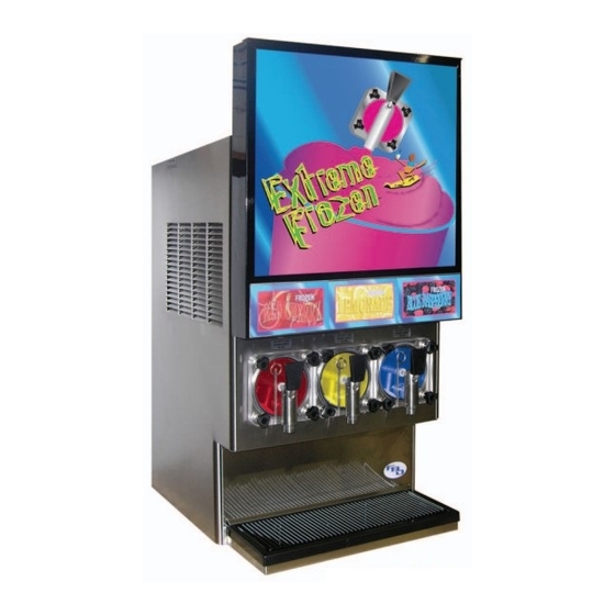
FROZEN BEVERAGE DISPENSER
DIMENSIONS
Width
Depth
Height (Countertop Unit With Door)
Height (Optional Roll Around Unit/Stand) 68.0 inches
WEIGHT
Shipping
Empty
Operational
WATER REQUIREMENTS
Minimum flowing pressure
Maximum static pressure
CARBON DIOXIDE (CO
Minimum pressure
Maximum pressure
The information contained in this document is subject to change without notice.
FBD MAKES NO WARRANTY OF ANY KIND WITH REGARD TO THIS MATERIAL, INCLUDING, BUT NOT LIMIT-
ED TO, THE IMPLIED WARRANTIES OF MERCHANTABILITY AND FITNESS FOR A PARTICULAR
PURPOSE. FBD shall not be liable for errors contained herein or for incidental consequential damages in connection with the
furnishings, performance, or use of this material.
This document contains proprietary information which is protected by copyright. All rights reserved.
THIS DOCUMENT CONTAINS IMPORTANT INFORMATION
This manual must be read and understood before the installation and operation of this dispenser.
This manual supersedes and replaces 24-2116-0001 dated 06/27/05.
• FBD TECHNICAL SUPPORT • 1-866-323-2777 • TECHNICAL SUPPORT FAX 1-210-637-2832
FOR THE
MODEL FBD553D
SPECIFICATIONS
20.25 inches
33.5 inches
41.4 inches
) REQUIREMENTS
2
© Copyright 2006 by FBD, all rights reserved.
FBD Partnership, LP
• P.O. BOX 18597. • SAN ANTONIO, TX 78218 USA •
• 210-637-2800 • FAX 210-637-2844 • www.fbdfrozen.com •
Please refer to the FBD web site (www.fbdfrozen.com) for
information relating to FBD Installation and Service Manuals,
Instruction Sheets, Technical Bulletins, Service Bulletins, etc.
(511 mm)
(851 mm)
(1054 mm)
(1727 mm)
415 pounds (188 kg)
365 pounds (165 kg)
390 pounds (177 kg)
30 PSIG
(206.8 KPa)
70 PSIG
(483.0 KPa)
70 PSIG
(483.0 KPa)
75 PSIG
(517.5 KPa)
NOTICE:
REV:
FBD Part Number: 24-2116-0001
10/25/06
Advertisement
Table of Contents

Related Manuals for FBD FBD553D


Summary of Contents for FBD FBD553D
- Page 1 FBD MAKES NO WARRANTY OF ANY KIND WITH REGARD TO THIS MATERIAL, INCLUDING, BUT NOT LIMIT- ED TO, THE IMPLIED WARRANTIES OF MERCHANTABILITY AND FITNESS FOR A PARTICULAR PURPOSE. FBD shall not be liable for errors contained herein or for incidental consequential damages in connection with the furnishings, performance, or use of this material.
-
Page 2: Table Of Contents
DAILY CLEANING OF THE UNIT ....................14 SANITIZING THE SYRUP SYSTEMS .....................14 9. BASICS OF OPERATION .........................15 MAKING ADJUSTMENTS TO THE FBD553D.................15 10. CHANGING FACTORY SET “LEVEL CONTROL” ..................16 10.1 BEFORE CHANGING “LEVEL CONTROL” SETTINGS..............16 10.2 DRINK TOO HARD AND COLD.......................17 10.3 DRINK TOO LIQUID ........................17... -
Page 3: Safety Precautions
15.20 DDV NOZZLE AND FACE PLATE ASSEMBLY................60 15.21 RETRO MERCHANDISER DOOR, FBD553 (7-11) ...............61 SAFETY PRECAUTIONS We at FBD are concerned about your safety. Please carefully read the following precautions before working with the FBD553D unit. This will familiarize you with proper equipment handling techniques. LIFTING •... -
Page 4: Preparing The Location
2 INCHES 12 INCHES LOCATION REQUIREMENTS 2 INCHES A. The operational FBD553D countertop unit weighs 390 pounds (177 kg) and requires a sturdy, level surface for placement. When selecting a counter location, ensure the counter will support the unit weight plus the weight of any additional equipment placed near it. -
Page 5: Roll Around Cart
mark and drill the four (4) mounting holes in the countertop. B. With the side panels removed, lift unit by the frame cross bracing and place unit on the counter. C. If permanently mounting the unit to a countertop, install four (4) 3/8-16 UNC bolts (not included) through the underside of the counter [through the four (4) mounting holes drilled in the step just above], and into the frame. -
Page 6: Connecting Water, Co
Figure 5.2 CAUTION: THE BACKFLOW PREVENTION DEVICE (FBD PN 12-2272-0001) MUST HAVE A DRAIN LINE CONNECTED TO THE VENT (SEE FIGURE 5.1). THIS IS REQUIRED TO DRAIN AWAY WATER IN THE EVENT OF A BACKFLOW SITUATION OR A FAILURE OF THE BACKFLOW DEVICE. -
Page 7: Syrup Supply
C. Splice a barb "cross" into the CO supply line and run two (2) lines to the syrup pump CO inlets. If Figal tank will be utilized, splice a barb "cross" into the CO supply line and run three (3) lines to tank location and install CO tank couplers to end of lines. -
Page 8: Brixing
F. With voltage meter, check voltage at contactor between L1 & L2 and record. Also check between L1 and ground bar, and between L2 and ground bar, to ensure highest voltage leg is on L1 (see Figures 6.2, 6.3, and Section 14.3). H. -
Page 9: Filling The Chamber
Figure 6.4 K. Measure the brix with a refractometer. Set brix to between 13.5 and 15.0 by adjusting the syrup brix flow controller clockwise to increase brix level or counter-clockwise to decrease brix level. If the brix requires adjustment, discard a sample before checking the brix again. NOTE Do not adjust the brix with the water flow control setting unless you are unable to obtain the desired brix with adjustments to the syrup flow control. -
Page 10: Critical Regulator And Flow Control Settings
CRITICAL REGULATOR AND FLOW CONTROL SETTINGS SET ALL PRESSURES USING THE LCD READOUTS ON THE UNIT - NOT BY THE GAUGES ON THE REGULATORS! PRIMARY REGULATOR The CO Primary Regulator MUST BE SET TO 70-72 PSIG (482.6 TO 496.4 KPa) [bulk tank set at 115-120 PSIG (793.5 - 828.0 KPa)]. SECONDARY REGULATOR The CO Secondary Regulator SHOULD BE SET AT 28-32 PSI... - Page 11 BEATER The BEATER button activates the beaters inside the freezing chambers. The beaters can be activated to mix the slurry. NOTE: The beaters start automatically when the RUN or DEF buttons are pressed. The DEF button allows the user to manually defrost chamber. Because the unit automatically defrosts during the day, it is not necessary to defrost manually.
- Page 12 optimize the operation of the machine. Incorrect settings at this level could prevent the machine from operating properly or cause damage to the unit. Included in this level are various accumulated totals and diagnostic tools that help the technician evaluate problems. NOTE To access the Service Menu, press the FWD button on the control panel until “SERVICE MENU”...
- Page 13 SELECT Figure 7.3...
-
Page 14: Machine Access
MACHINE ACCESS (SEE FIGURE 7.2) A. Machine Operator Display Mode Display Description Preset Value 1. VERSION Shows current version of the software installed. 2. TIME Used to set the time of day. The machine uses a 24 hour format (military time) clock. The clock has a battery backup which maintains correct time even if not plugged into electrical power. -
Page 15: Machine Settings
MACHINE SETTINGS These settings are preset by the machine. DO NOT change unless there is a problem with drink quality. Mode L Side Settings Level Control = 3 The higher the value, the higher the product level Center Settings in the chamber. R Side Settings The lower the value, the lower the product level in the chamber. -
Page 16: Readouts
If other equipment is being cleaned, follow the guidelines established for that equipment. A. FBD equipment (new or reconditioned) is shipped from the factory, cleaned and sanitized in accordance with NSF guidelines. After installation is complete, the operator of the equipment must provide continuous maintenance as required by this manual and/or state and local health department guidelines to ensure proper operation and sanitation requirements are maintained. -
Page 17: Required Cleaning Equipment
C. Place a container under the valve and empty the barrels. Activate the beaters to facilitate the removal of product. D. Disconnect the BIB connectors from the syrup boxes and install BIB adapters (FBD PN 05-0249) onto the BIB connectors. Activate the right, center, and left solution solenoids at the "SERVICE MENU/MANUAL ON/OFF"... -
Page 18: Basics Of Operation
MAKING ADJUSTMENTS TO THE FBD553D A. In order to produce a consistent, quality beverage with the FBD553D Frozen Beverage Machine, there are a few critical settings that must be maintained. These settings are preset when you receive the machine from the factory, but, due to variations that occur (e.g., in operating... -
Page 19: Changing Factory Set "Level Control
2. “Level Control” a. The FBD553D frozen beverage dispenser utilizes a proprietary liquid level control system (patented) to hold a constant liquid level. A constant liquid level assures a quality frozen product. b. If a more “wet” product is desired, the numerical setting (0-6) should be increased. If a “drier”... -
Page 20: Drink Too Hard And Cold
B. Before making any changes to the level control settings, defrost all three chambers by pressing the “DEF” buttons located on the control panel. The machine may automatically correct any problems with drink quality after going through a defrost cycle. C. -
Page 21: Changing The Default Level Control Setting
10.4 CHANGING THE DEFAULT LEVEL CONTROL SETTING A. The level control setting is preset at the factory at a value of 3. B. If the drink is not frozen enough, or if the drink is too hard and too cold and dispenses slowly, after the machine has been running for 10 to 15 minutes, it may be necessary to adjust the level control settings. -
Page 22: Changing Thaw And Freeze Settings
10. When settings are complete, press the “CANCEL” button until “Copyright” displays. 12. BEVTRAK OPERATION Bevtrak is a feature on the FBD553D that enables the unit to dial a toll free number every night and download current status information about the unit as well as daily sales numbers. The information is collected and cataloged on the FBD server and is readily available to subscribers via the Internet. -
Page 23: Normal Operation
(Continued from previous page) Timeout m = 3 (Timeout minutes) - The amount of time the unit will wait from the start of a call to the completion of the call. If the call has not completed by then it will hang up. Bt manual = 0 (Bevtrak manual mode) In the Manual mode (=1) the unit will schedule calls at the call period after the call delay. -
Page 24: Line Voltage Drop
828.0 KPa). A secondary regulator will be necessary for pumps (syrup, water) to avoid exceeding manufacturer’s recommended operating pressures. 14. TROUBLESHOOTING GUIDE The following information is a listing of the most common problems that could keep the FBD553D Dispenser from operating properly. Contact the factory for details, when necessary. TROUBLE... - Page 25 TROUBLE CAUSE REMEDY (Section 14.2 continued from previous page.) B. Solution solenoid energized. B. Test solenoid relay on relay board for 24VAC output and 5VDC relay coil input. Replace Relay Board, if necessary. C. Solution solenoid left “ON” C. In “Manual On/Off”, turn “solenoid in “Manual”.
-
Page 26: Electrical
TROUBLE CAUSE REMEDY (Section 14.4 continued from previous page.) E. Product in cylinder is frozen E. 1. Check water/syrup flow too hard or solid. rates and brix. Adjust, if necessary (see Section 6.2). 2. Check Level Control setting. Adjust if necessary (see Section 10). - Page 27 TROUBLE CAUSE REMEDY 14.10 Solenoids continuously A. Solenoid plunger not dropping. A. In “Manual On/Off”, energize activated. solenoid on and off checking for plunger movement and 24VAC at coil. Clean or replace solenoid, if necessary. B. Solenoid Relay stuck. B. Test solenoid relay on Relay Board through manual ON/OFF menu.
-
Page 28: Electronic Controls
TROUBLE CAUSE REMEDY ELECTRONIC CONTROLS 14.17 LCD readout garbled A. Voltage spike or noise. A. Press “CANCEL” several times. or blank. B. Low or no voltage to unit or B. Check L1 & L2 of contactor for loss of 5VDC signal. 220 VAC and test points on lower and upper board for +5 VDC (see Figure 14.3). - Page 29 14.23 High head/suction A. Condensor air flow restricted. A. Check for air flow restriction, clean pressure. Contact condensor and air filter. FBD Warranty Dept. B. Compressor damage B. Check amp draw on compressor before tapping system (normal running 18 amps).
-
Page 30: Drink Quality
CAUSE REMEDY 14.24 Low head/suction A. Low refrigerant level. A. See item 14.22.H above. pressure. Contact FBD Warranty Dept. B. Compressor damage. B. Check amp draw on compressor before tapping system (normal running 18 amps). if unit is under warranty! DRINK QUALITY 14.25 Drink too “Wet”... - Page 31 TROUBLE CAUSE REMEDY (Section 14.26 continued from previous page.) E. “THAW/FREEZE” settings E. Raise the “THAW/FREEZE” set too low. settings using the instructions in Section 11.2 of this manual. F. Volumetric Valve F. Activate "Solution Disp" in Manual malfunctioning and not On/Off and check for flow.
-
Page 32: Lcd Display Error Messages
TROUBLE CAUSE REMEDY (Section 14.29 continued from previous page.) E. Level Control too low. E. Level Control settings may need to be raised due to excessive CO the chamber. Raise the Level Control settings using the instructions in Section 10.2 of this manual. - Page 33 TROUBLE CAUSE REMEDY (Section 14.34 continued from previous page.) F. Syrup Transducer problem. F. Check syrup pressure readouts for 70-72 psi . If not within 2 psi, adjust regulator and/or check transducer. Replace transducer, if necessary. G. Lower Board problem. G Test lower board for +5, +15, and –15 outputs on lower board test points (see Figure 14.3).
- Page 34 TROUBLE CAUSE REMEDY (Section 14.36 continued from previous page.) G. Upper Board Problem. G. Circuits within Main Control (Upper) Board electronics read transducer pressures. Replace Main Control (Upper) Board, if necessary 14.37 RtnTempErr A. Temperature Sensor error A. 1. Check for short in sensor and or failure.
-
Page 35: Lcd Display Messages
LCD DISPLAY MESSAGES FBD553D FROZEN BEVERAGE DISPENSER MESSAGE DESCRIPTION Sleeping Unit in “Sleep” mode. Unit is shut down. Cmpr StDly This delay is before compressor starts. The time period varies from 1 to 30 seconds. Cmpr Start This is displayed when compressor starts freezing or defrosting. -
Page 36: Lcd Display Error Messages
LCD DISPLAY ERROR MESSAGES FBD553D FROZEN BEVERAGE DISPENSER MESSAGE DESCRIPTION DEFPresMax Chamber pressure is above 55 PSIG during defrost only. DEFProdOut Product is out during defrost only. BTR-LO-ERR Low beater percent. Below 450%. BTR-HI-ERR High beater percent. Above 1200%. SYRUP OUT Syrup pressure is below 45 PSIG. -
Page 37: Illustrations, Parts Listings, And Diagrams
15. ILLUSTRATIONS, PART LISTINGS, AND DIAGRAMS 15.1 MOUNTING DIAGRAM This Figure illustrates the locations of threaded mounting holes in the base of the FBD553D machine. 1.0" 22.0" EDGE OF MACHINE EDGE OF MACHINE 34.50" 16.75" 1.75" USE 1/2" DRILL BIT (4 HOLES) 11.50"... -
Page 38: Flow Diagram/Schematic
15.2 FLOW DIAGRAM/SCHEMATIC... -
Page 39: Electrical/Schematic-01
15.3 ELECTRICAL/SCHEMATIC-01 MAIN AC-P1 CONTACTOR, 2POLE 30AMP COIL A COMPRESSOR 230VAC LINE INPUT OUTPUT 230 VAC NEU COIL B MAIN GROUND DIAGRAM CONTACTOR, 2POLE 30A COIL A COIL B L6-30P START CAP. Line 189-227 uF @ 250 VAC Common WHT/RED STARTER RELAY RUN CAP. -
Page 40: Electrical/Schematic-02
15.4 ELECTRICAL/SCHEMATIC-02 L SOL C SOL R SOL R CO2 L CO2 C CO2 CNTLR P7 CNTLR P6 GAS 3 24VAC RTN WHT/RED 24VAC 24VAC WHT/RED 24VAC 24VAC RTN SOL 3 24VAC SOL 2 GAS 2 GAS 1 SOL 1 L DEF C DEF R DEF...
Need help?
Do you have a question about the FBD553D and is the answer not in the manual?
Questions and answers