
Related Manuals for Mitsubishi Electric PEFY-P20VMR-E-L


Summary of Contents for Mitsubishi Electric PEFY-P20VMR-E-L
- Page 1 2006 Air-Conditioners For Building Application TECHNICAL & SERVICE MANUAL PEFY-P20VMR-E-L/R Models PEFY-P25VMR-E-L/R PEFY-P32VMR-E-L/R For use with R410A...
-
Page 2: Safety Precautions
Have all electrical work performed by an authorized Only use accessories (i.e., air cleaners, humidifiers, electric electrician according to the local regulations and the heaters) recommended by Mitsubishi Electric. instructions in this manual. Use a dedicated circuit. Insufficient power supply capacity or improper installation of the unit may result in malfunctions of the unit, electric shock, or fire. - Page 3 When installing the unit in a small space, take appropriate recommended by Mitsubishi Electric may result in smoke, precautions to prevent leaked refrigerant from reaching the fire, or explosion.
-
Page 4: Table Of Contents
CONTENTS [1] FEATURES Features............................1 [2] COMPONENTS AND FUNCTIONS Components and functions ......................2 [3] SPECIFICATIONS 3-1. Specifications ........................4 3-2. Electrical component specifications..................5 [4] OUTLINES AND DIMENSIONS PEFY-P20· 25· 32VMR-E-L/R ....................... 6 [5] WIRING DIAGRAM PEFY-P20· 25· 32VMR-E-L/R ....................... 7 [6] REFRIGERANT SYSTEM DIAGRAM Refrigerant system diagram...................... -
Page 5: Features
[ I FEATURES ] I FEATURES [1] FEATURES Cooling capacity/Heating capacity Model PEFY-P20VMR-E-L/R 2.2/2.5 PEFY-P25VMR-E-L/R 2.8/3.2 PEFY-P32VMR-E-L/R 3.6/4.0 - 1 -... -
Page 6: Components And Functions
[ II COMPONENTS AND FUNCTIONS ] II COMPONENTS AND FUNCTIONS [2] COMPONENTS AND FUNCTIONS Indoor (Main) Unit [PAR-21MAA] Remote controller Once the operation mode is selected, the unit will remain in the selected mode until changed. [Remote Controller Button] [Set Temperature] Button [Timer Menu] Button [Mode] Button [Monitor/Set] Button... - Page 7 [ II COMPONENTS AND FUNCTIONS ] [Remote Controller Display] TIME MON TUE WED THU FRI TIMER AFTER AFTER ERROR CODE FUNCTION °F °C FILTER ° F ° C WEEKLY SIMPLE ONLY 1Hr. AUTO OFF TEMP. ON/OFF Current time/Timer time Centralized control indicator Timer OFF indicator Timer mode Operation mode display:...
-
Page 8: Specifications
[ III SPECIFICATIONS ] III SPECIFICATIONS [3] SPECIFICATIONS 3-1. Specifications Model PEFY-P20VMR-E-L/R PEFY-P25VMR-E-L/R PEFY-P32VMR-E-L/R Cooling capacity *1 Heating capacity *1 Power supply voltage/frequency Single-phase 220/230/240 V 50Hz 220/230 V 60Hz Cooling 0.06/0.06 0.07/0.08 Power consumption Heating 0.06/0.06 0.07/0.08 Cooling 0.29/0.29 0.34/0.38... -
Page 9: Electrical Component Specifications
[ III SPECIFICATIONS ] 3-2. Electrical component specifications Model Symbol PEFY-P20VMR-E-L/R PEFY-P25VMR-E-L/R PEFY-P32VMR-E-L/R Component Transformer (Primary) 50/60Hz 220-240V (Secondry) (23.5V 0.9A) Room temperature TH21 Resistance 0°C/15kΩ, 10°C/9.6kΩ, 20°C/6.3kΩ, 25°C/5.4kΩ, 30°C/4.3kΩ, 40°C/3.0kΩ thermistor Liquid pipe TH22 Resistance 0°C/15kΩ, 10°C/9.6kΩ, 20°C/6.3kΩ, 25°C/5.4kΩ, 30°C/4.3kΩ, 40°C/3.0kΩ... -
Page 10: Outlines And Dimensions Pefy-P20· 25· 32Vmr-E-L/R
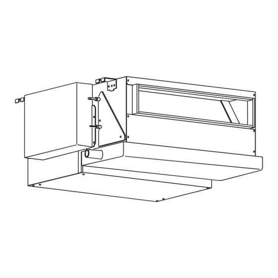
[ IV OUTLINES AND DIMENSIONS ] IV OUTLINES AND DIMENSIONS [4] OUTLINES AND DIMENSIONS PEFY-P20· 25· 32VMR-E-L/R (A) Space required for service and maintenance (Note 2) (B) Provide an access door as shown in the figure for maintenance. Note 1. Use M10 suspension bolts. (not supplied) 2. -
Page 11: Wiring Diagram Pefy-P20· 25· 32Vmr-E-L/R
[ V WIRING DIAGRAM ] V WIRING DIAGRAM [5] WIRING DIAGRAM PEFY-P20· 25· 32VMR-E-L/R - 7 -... - Page 12 [ V WIRING DIAGRAM ] [5] WIRING DIAGRAM The fan motor connector is ready for connection to a 220V/230V power supply at factory shipment. Use blue connector adapter (supplied) to connect to a 240V power supply. Coler/Power supply voltage White/220V. 230V Blue/240V NOTE: 1.
-
Page 13: Refrigerant System Diagram
[ VI REFRIGERANT SYSTEM DIAGRAM ] VI REFRIGERANT SYSTEM DIAGRAM [6] REFRIGERANT SYSTEM DIAGRAM Gas pipe thermistor TH23 Gas pipe Liquid pipe thermistor TH22 Brazed connections Strainer (#100 mesh) Heat exchanger Linear expansion valve Room temperature thermistor TH21 Capacity PEFY-P20, 25, 32VMR-E-L/R Gas pipe ø12.7<1/2>... -
Page 14: Troubleshooting
[ VII TROUBLESHOOTING ] VII TROUBLESHOOTING [7] TROUBLESHOOTING 7-1. Check methods 1. Component and Check points (1) Thermistor • Room temperature thermistor (TH21) • Liquid pipe thermistor (TH22) • Gas pipe thermistor (TH23) Disconnect the connector, and measure the resistance with a tester. (Ambient temperature 10°C-30°C) Normal Abnormal... - Page 15 [ VII TROUBLESHOOTING ] (4) Linear expansion valve White Yellow Orange Blue Brown Disconnect the connector, and measure the resistance with a tester. Normal Abnormal (1)-(5) (2)-(6) (3)-(5) (4)-(6) White-Red Yellow-Brown Orange-Red Blue-Brown Open or short 150Ω ±10% <Thermistor characteristic graph> Room temperature thermistor (TH21) Liquid pipe thermistor (TH22) Gas pipe thermistor (TH23)
-
Page 16: Address Switch Setting
[ VII TROUBLESHOOTING ] Make sure that power to the unit is turned off. 7-2. Address switch setting Indoor unit control board <Factory setting (All models)> <Factory setting (All models)> 1 2 3 4 5 6 7 8 910 1 2 3 5 4 Refer to the next page for setting dipswitches SW2 and SW3. -
Page 17: Dipswitch Setting (Factory Setting)
[ VII TROUBLESHOOTING ] 7-3. Dipswitch setting (Factory setting) Group No. Models PEFY-P20VMR-E-L Option 220 V Standard 240 V PEFY-P20VMR-E-R PEFY-P25VMR-E-L Option 220 V Standard 240 V PEFY-P25VMR-E-R 1 2 3 4 5 6 7 8 910 PEFY-P32VMR-E-L Option 220 V... -
Page 18: Disassembly Procedure
[ VIII DISASSEMBLY PROCEDURE ] VIII DISASSEMBLY PROCEDURE Exercise caution when removing heavy parts. [8] DISASSEMBLY PROCEDURE 8-1. Control box 1. Removing the control box cover Fig. 1 Remove the two fixing screws on the control box, and remove the Control box cover. -
Page 19: Fan And Fan Motor
[ VIII DISASSEMBLY PROCEDURE ] Exercise caution when removing heavy parts. 8-2. Fan and fan motor 1. Removing the fan casing, sirocco fan, and fan motor Fig. 3 (1) Remove the filter. (Fig. 3) Filter (2) Open the control box to remove the fan motor cable Fig. -
Page 20: Drainpan
[ VIII DISASSEMBLY PROCEDURE ] Exercise caution when removing heavy parts. 8-3. Drainpan 1. Removing the drainpan Fig. 7 (1) Remove the one fixing screw on the drainpan. (Fig. 7) (2) Slide the drainpan in the order as indicated with arrows Fig. -
Page 21: Lev, Thermistor (Liquid/Gas Pipe)
[ VIII DISASSEMBLY PROCEDURE ] Exercise caution when removing heavy parts. 8-4. LEV, thermistor (Liquid/gas pipe) 1. Removing the LEV Fig. 9 (1) Remove the drainpan according to the procedure in section 8-3. (2) Remove the bottom plate by unscrewing the six fixing screws. -
Page 22: Heat Exchanger
[ VIII DISASSEMBLY PROCEDURE ] Exercise caution when removing heavy parts. 8-5. Heat exchanger 1. Removing the heat exchanger Fig. 12 (1) Remove the drainpan according to the procedure in section Heat exchanger 8-3. cover (2) Remove the bottom plate according to the procedure in section 8-4. -
Page 23: Control Box Internal Layout
[ VIII DISASSEMBLY PROCEDURE ] 8-6. Control box internal layout Indoor unit control board Fan motor connector Address board Primary CN31 SW14 SW12 SW11 DSA board Connector adapter Capacitor (for motor) Secondary CN42 Transformer Transmission terminal block Power supply terminal block MA Remo.Con. - Page 24 Oct. 2006 HWE06010 New publication, effective Oct. 2006 Printed in Japan Specifications subject to change without notice...
Need help?
Do you have a question about the PEFY-P20VMR-E-L and is the answer not in the manual?
Questions and answers