LiveU LU60 User Manual

LiveU LU60 User Manual

Live video uplink system
Table of Contents

Advertisement

LiveU Live Video
Uplink System
User Guide
(LU60 and LU70)
Version 6.3
Part Number: DOC00032

Advertisement

Table of Contents
loading

Summary of Contents for LiveU LU60

  • Page 1: About This Guide

    LiveU Live Video Uplink System User Guide (LU60 and LU70) Version 6.3 Part Number: DOC00032...
  • Page 2 LiveU Live Video Uplink System User Guide About This Guide This guide describes the LU60/LU70 live video uplink system and provides basic operation information for camera operators. It describes the hardware that is included and how to use the system in order to broadcast live streaming video for a multitude of purposes.
  • Page 3 LU's video output and hands-on instruction for broadcasting via a number of different applications. The LiveU Xtender option can also be used with LU60/LU70 units to increase network reception and provide additional resiliency for live video transmission...
  • Page 4: Table Of Contents

    LU60/LU70 Hardware Components ..............17 Chapter 2: Getting Started ..................19 Step 1, Turning On the LU Device ................20 LU60/LU70 – Turning On the Device ..............20 Main User Window ....................22 Step 2, Connecting the Video Camera ..............23 LU60/LU70 –...
  • Page 5 Table of Contents Options Button ....................... 44 Upload Button ........................ 44 Connect/Reconnect Button ..................44 Connect Button ...................... 43 Reconnect Button ....................44 Transmit Button ....................... 45 Profiles ..........................46 Platform and Unit Name ....................45 Chapter 4: Successful Video Transmission ............. 47 Overview .........................
  • Page 6 What Cannot be Controlled Remotely ..............117 Appendix A: LU Battery ..................119 The LU60/LU70 Battery ....................119 Checking the LU60/LU70 Battery Charge ............120 Charging the LU60/LU70 Battery ............... 121 Changing the LU60/LU70 Battery ..............122 Appendix B: LU Backpack ..................125 The LU60/LU70 Backpack ...................
  • Page 7: Table Of Figures

    Figure 5: LU Main User Interface – Without Camera ............23 Figure 6: LU60/LU70 with SDI Camera Connection ............24 Figure 7: LU60/LU70 with DV, HDMI and Analog Camera Connection ...... 24 
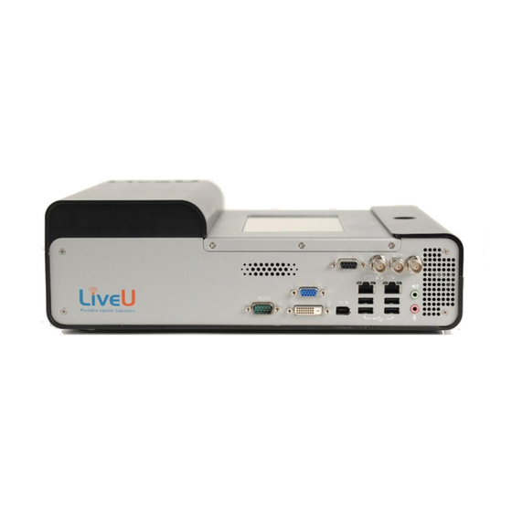
Figure 8: LU Video Uplink Unit Connections ..............25 Figure 9: Connecting to an Interface ................
  • Page 8 LiveU Live Video Uplink System User Guide Figure 30: Profiles Window ....................49 Figure 31: Profiles Window ....................50 Figure 32: Interview Profile ....................51 Figure 33: Balanced Profile ....................53 Figure 34: Max Quality Profile ..................... 54 Figure 35: Changing a Profile’s Resolution ............... 56 Figure 36: LU File Transfer .....................
  • Page 9 Figure 80: Utilities Settings ....................99 Figure 81: Input Media Settings ..................101 Figure 82: Startup Operation Settings ................102 Figure 83: Getting Remote Support from LiveU ............103 Figure 84: Power Options ....................104 Figure 85: Installing Remote Control – 1 ................. 106 Figure 86: Installing Remote Control –...
  • Page 10 Figure 101: Battery Status Tool Tip ..................120 Figure 102: Battery Indication Light ................. 120 Figure 103: LU60/LU70 Video Uplink Unit – Top View ............ 121 Figure 104: Opening the Battery Compartment – Lifting the Tab ......122 Figure 105: Opening the Battery Compartment – Pulling Open the Cover .... 122 Figure 106: Pulling Out the Battery ..................
  • Page 11: Support And Contacting Information

    2 University Plaza Drive Suite 505 Hackensack, New Jersey, 07601 Tel: 1-(201)-742-5228 Fax: 1-(201)-623-4838 USA and the Americas: info_us@liveu.tv International: info@liveu.tv Technical Support: ► For 24/7 support, call: US and Latin America: Tel: 1-(877)-88-LiveU (54838) Email: help@liveu.tv International: Tel: 1-(609)-997-0600 Email: support@liveu.tv...
  • Page 12 LiveU Live Video Uplink System User Guide Blank page for double-sided printing...
  • Page 13: Chapter 1: Overview

    You can use this device to increase network reception of the LiveU LU60/LU70 units to which it is connected. Contact LiveU for more details about purchasing this option. The LiveU...
  • Page 14: System Overview

    LiveU Live Video Uplink System User Guide System Overview The LU Live Video Uplink unit simultaneously aggregates a number of networking infrastructures (cellular, Wi-Fi and so on) in order to stream live audio and video from field locations to the LU-1000 central server, which is usually located in a broadcasting center.
  • Page 15: Wireless Connectivity

    Overview Wireless Connectivity The LU unit is designed to search for and connect to whichever cellular, wireless or Ethernet (LAN) data infrastructures are available. The system has several built-in interfaces that are able to establish a connection to many different networks simultaneously in order to overcome inherent bandwidth limitations and offer robust transmissions.
  • Page 16: Lu As An Access Point

    The LU60/LU70 family supports up to 1080 full HD video. The LU60/LU70 devices may be provided with one of the following video input options: •...
  • Page 17: What's In The Box

    Overview What’s in the Box? The following describes the components provided in the box for the LU60/LU70 family of devices. LU60/LU70 Hardware Components The LU60/LU70 Live Video Uplink system consists of the following components: • The LU60/LU70 Mobile field unit. Two LU60/LU70 configurations are...
  • Page 18 LiveU Live Video Uplink System User Guide Blank page for double-sided printing...
  • Page 19: Chapter 2: Getting Started

    Getting Started This chapter describes how to get started using the LU, including powering on, connecting the camera, connecting to the LU-1000 and broadcasting (playing). The following is an overview of the workflow described in this chapter. NOTE You may connect non-DV cameras to the LU before turning on the LU. Turning on the LU Device Step 1 Page 20...
  • Page 20: Step 1, Turning On The Lu Device

    LiveU Live Video Uplink System User Guide Step 1, Turning On the LU Device The following describes the procedure for turning on the LU60/LU70 family of devices. LU60/LU70 – Turning On the Device The LU60/LU70 device is provided by LiveU with a charged battery already inserted.
  • Page 21: Figure 2: Power Switch On

    To turn on the LU60/LU70 unit: ► NOTE Do not connect a DV camera before powering up the LU60/LU70. Press and hold the power switch for approximately two seconds until it lights Figure 2: Power Switch On It is good practice to keep the unit plugged into a power outlet when it is not in use in order to keep it charged and ready for operation.
  • Page 22: Main User Window

    LiveU Live Video Uplink System User Guide Main User Window After a boot-up period, the touch-screen becomes active, and the user interface appears, as shown below. If the camera has been connected, powered on and then automatically detected by the LU, a preview of the video feed is automatically displayed in the center of the main window, as shown below: Figure 4: LU Main User Interface –...
  • Page 23: Step 2, Connecting The Video Camera

    LU unit. Such devices are sometimes called Quad. However, even if more than one camera is connected in this manner, only one feed from one camera at a time is recognized and transmitted. The following describes the procedure for connecting a camera to the LU60/LU70.
  • Page 24: Lu60/Lu70 - Connecting The Camera

    LiveU Live Video Uplink System User Guide LU60/LU70 – Connecting the Camera Different models of the LU60/LU70 are provided, each with the ability to connect to different cameras. All models connect to DV (FireWire 1394) cameras. The following LU60/LU70 unit connection options are available:...
  • Page 25: Figure 8: Lu Video Uplink Unit Connections

    (FIREWIRE) use the LiveU provided FireWire/DV (1394E) cables! CAMERAS LiveU provides two types of FireWire/DV (1394E) cables: one type connects 4 pins to 6 pins, where the power is connected, and the other type connects 6 pins to 6 pins.
  • Page 26: Step 3, Connecting To The Lu-1000

    LiveU Live Video Uplink System User Guide For DV cameras, after the camera is attached to the unit, you can connect an external power supply to the camera, if needed. Then, turn the camera The camera video is automatically displayed on the unit’s screen, if the camera is on and properly configured.
  • Page 27: Figure 10: Connecting Status Indicator

    Getting Started The Connecting status indicator is displayed, as shown below: Figure 10: Connecting Status Indicator Even though the LU can operate without all interfaces, it retries connecting a number of times before giving up and displaying the following message: Figure 11: Interface Connection Failed After the modems are connected, the system carries out network-related tests and the application automatically calibrates the available bandwidth...
  • Page 28: Connecting - Transmission Test

    LiveU Live Video Uplink System User Guide Connecting – Transmission Test In order to accurately calculate and grade the modems and their broadcasting efficiency, the LU automatically transmits a LiveU pre-stored video stream. During transmission, the following window appears showing the transmitted video: Figure 12: Connecting –...
  • Page 29: Figure 14: Unsupported Resolution

    Getting Started NOTE During installation, you can choose SD or HD configuration. For HD configuration, the LU is installed with HD, without inserting a camera. Only LU products with HD support display the HD tab, shown above. The Profiles and Resolutions that are available for selection are displayed with (green).
  • Page 30: Step 4, Playing

    LiveU Live Video Uplink System User Guide Step 4, Playing Tap Transmit to start broadcasting live streaming video to the broadcasting center. You can tap the Transmission Strength indicator to display the number of Kb/s transmitted and received, as shown below:...
  • Page 31: Checking Interface Quality

    Getting Started Checking Interface Quality It is not mandatory, but you may want to check the quality of your interfaces before starting transmission, meaning before pressing the Transmit button. You may also decide to check the quality of the interfaces after a long time has passed since calibration was performed (meaning since the Connect button was pressed) or immediately after transmission conditions have changed (for example, from stationary to driving).
  • Page 32 73. NOTE The LU60/LU70 products that support dual SIM are provided with modules. A module has two rows of SIM cards: A and B. Two SIM cards of each type are on the module, one on each row. Only one row of SIM cards is used at a time.
  • Page 33: Chapter 3: Lu User Interface

    LU User Interface This chapter describes the main LU window and the options that it provides. This chapter contains the following sections: • LU Touch-screen Interface, page 34 • Video Feed, page 35 • Camera Connectivity Icon, page 36 • Battery Indicator Icon, page 37 •...
  • Page 34: Lu Touch-Screen Interface

    LiveU Live Video Uplink System User Guide LU Touch-screen Interface The Live Video Uplink User unit’s user interface is an LCD touch-screen. This main window automatically displays when the unit is ready. This touch-screen shows the video feed in its center and provides various buttons and indicators for controlling the unit and its broadcast.
  • Page 35: Video Feed

    LU User Interface Video Feed The center of the main window automatically shows a preview of the video feed after the camera is connected, turned on. The video feed is displayed a few seconds after the camera is connected and automatically detected by the Figure 19: Video Feed NOTE The video is only transmitting after you tap the Play button and the...
  • Page 36: Camera Connectivity Icon

    Table 1: Camera Connectivity Indicator Icon Status Description Icon Indicates that an HD camera is connected. This feature only appears for LU60/LU70 devices that support HD. Indicates that a standard camera is connected. Indicates that no camera is connected.
  • Page 37: Battery Indicator Icon

    LU User Interface To display information about the connected camera: ► • Tap on the Camera Connectivity icon to display a tool tip of information. The following tool tip shows the camera’s type and resolution: Figure 21: Camera Tool Tip Battery Indicator Icon The Battery indicator shows the battery’s current status.
  • Page 38: Transmission Quality

    There is a small LCD indicator that shows up to five bars. You may refer to Checking the LU60/LU70 Battery Charge section on page 120 for a description of the battery charge indicator in the battery compartment.
  • Page 39: Ifb Indicator

    LU User Interface IFB Indicator IFB (Interrupted Feedback) feature enables an LU operator to listen to an audio channel received from an IFB server using an earphone, even while broadcasting. Typically, this type of communication is used to receive verbal instructions or information about events.
  • Page 40: Figure 25: Ifb Configuration Window

    LiveU Live Video Uplink System User Guide Tapping the IFB button displays the following window: Figure 25: IFB Configuration Window To configure the IFB channel: ► Select one of the IFB channels provided by the IFB server from the displayed list.
  • Page 41: Status Indicator

    LU User Interface By default, the IFB is not muted. You can select the Mute (or Unmute) button. You can click the Stop button to close the IFB channel. Figure 26: IFB Channel Open Status Indicator The status icon at the top of the window provides information about the connection and transmission status of the LU.
  • Page 42: Rotate Screen

    LiveU Live Video Uplink System User Guide Status Icon Description On-Air (green light). Appears when the system is connected and video is being transmitted correctly. Forwarding (green light). Appears when a stored session is being forwarded. Error (yellow light). Appears when an error occurs. You...
  • Page 43: Options Button

    LU User Interface Options Button This button displays information about the broadcasting interfaces, configuration settings and channels. It also enables you to access remote support and to restart or power down the unit. A full description of the options provided by this button is in Chapter 7, Configuration and Settings on page 73. Upload Button This button enables you to store prerecorded files, transfer prerecorded files or simultaneously store and forward the prerecorded files to the LU-1000 server.
  • Page 44: Connect/Reconnect Button

    LiveU Live Video Uplink System User Guide Reconnect Button After the Connect button is tapped and a connection has been established, the button’s name changes on the display to Reconnect. This means that the LU is connected to the LU-1000 server.
  • Page 45: Profiles

    A full description about the Profiles provided for the LU and how to select them is provided in the Profiles Window section on page 48. Platform and Unit Name Tap the LiveU logo to display the following window showing the LU’s platform and unit name.
  • Page 46 LiveU Live Video Uplink System User Guide Blank page for double-sided printing...
  • Page 47: Chapter 4: Successful Video Transmission

    Successful Video Transmission This chapter describes some of the aspects on which successful transmission of a high-quality audio/video stream depend, such as video resolution, target resolution, bitrate, CODEC and so on. This chapter contains the following sections: • Overview, page 47 •...
  • Page 48: Profiles Window

    LiveU Live Video Uplink System User Guide The main factors when deciding target resolution are the quality of the broadcast and the delay. For example, if the event is a sporting event (Olympics, a ball game and so on), then it is important to use the highest bitrate available.
  • Page 49: Figure 30: Profiles Window

    Successful Video Transmission LU products that support High Definition (HD) automatically detect whether an the HD or HD or a Standard (SD) camera is connected. For these devices, SD option is automatically selected in the window below. In addition, the preconfigured Profile (Interview, Balanced or Max Quantity) and Video Resolution is automatically selected (such as Full D1 or Web HD).
  • Page 50: Changing The Profile

    LiveU Live Video Uplink System User Guide Changing the Profile Changing the selected Profile changes the basic characteristics of the broadcast (such as quality and/or delay). IMPORTANT There are limitations to when changes can be made. You cannot select whether to enable/disable modems on the fly.
  • Page 51: Profile Descriptions

    Successful Video Transmission Profile Descriptions The following describes the features and benefits of each Profile: • Interview Profile, page 51 • Balanced Profile, page 52 • Max Quality Profile, page 54 Interview Profile Select the Interview Profile when you need a short end-to-end delay. This Profile provides the maximum quality within the restriction of the shortest delay.
  • Page 52 LiveU Live Video Uplink System User Guide This Profile is more resilient to changes (errors) and adapts quickly to bandwidth changes. It is designed not to freeze. However, the quality may drop if networks conditions worsen abruptly. IMPORTANT The Interview Profile includes an automatic mechanism that activates when the network conditions worsen significantly.
  • Page 53: Figure 33: Balanced Profile

    Successful Video Transmission Balanced Profile Select the Balanced Profile when the delay starts to become important, yet an Interview delay is not mandatory. This setting provides high image quality with medium end-to-end delay. This Profile does not have a configurable custom delay.
  • Page 54: Figure 34: Max Quality Profile

    LiveU Live Video Uplink System User Guide Max Quality Profile This Profile is selected by default. Select the Max Quality Profile when the quality is of prime importance and the delay is not important. Figure 34: Max Quality Profile This Profile provides the best image quality at a potentially higher end-to-end delay.
  • Page 55: Changing A Profile's Resolution

    Successful Video Transmission You can manually set the delay and override the system’s automatic recommendation by checking the Custom delay checkbox. The system then displays the upper and lower permitted delay limits according to the performance of the Interfaces measured in the Calibration process during the Connect phase.
  • Page 56: Resolution Descriptions

    Resolution Descriptions The same resolutions are provided for each of the three Profiles, as follows: LU60/LU70 devices that support HD provide either four High Definition (HD) or four Standard Definition (SD) Resolutions for each of the three Profiles according to the camera that is connected.
  • Page 57 Successful Video Transmission HD (High Definition) The following resolutions are available for an HD video source on an LU60/LU70 device. • Web HD: 512x288: This is normally used for Internet output applications as well as TV under certain conditions. The optimal encoding bitrate for Web HD is between 350 and 750 Kbps (or up to 1.5 Mbps total...
  • Page 58 LiveU Live Video Uplink System User Guide SD (Standard Definition) The following resolutions are available for an SD video source on LU60/LU70 devices. • CIF: NTSC 360x240 | PAL 360x288: This is normally used for Internet output applications, as well as TV under certain conditions. The optimal encoding bitrate for CIF is between 350 and 750 Kbps (or up to 1.5 Mbps...
  • Page 59: Chapter 5: File Transfer

    File Transfer This chapter describes how to use the LU to transfer files from the field directly to the LU-1000 server. Transferring Files The LU Live Video Uplink System enables you to transfer prerecorded files to the LU-1000 server so that they may be saved for future use. This feature can also be used to transfer any other type of file, such as text files, documents and so on.
  • Page 60: Figure 36: Lu File Transfer

    LiveU Live Video Uplink System User Guide Tap the Upload button and then tap the File Transfer tab to display the following window: Figure 36: LU File Transfer The Status icon changes to transferring in order to indicate that the system is in File Transfer mode.
  • Page 61: Figure 37: Completed File Transmission

    File Transfer You can tap the Select Folder button to display a list of folders. You can then select one or more folders and tap the right arrow button move the folder(s) to the list on the right. These are the folders that can be transferred to the LU-1000 server.
  • Page 62 LiveU Live Video Uplink System User Guide Blank page for double-sided printing...
  • Page 63: Chapter 6: Store & Forward

    Store & Forward This chapter describes how to use the LU Store & Forward feature to record video sessions, forward them to the LU-1000 server, or simultaneously record and forward files from the field directly to the LU-1000 server. Storing and Forwarding Files The LU Live Video Uplink System enables you to store recorded files, transfer prerecorded files or simultaneously store and forward the recorded file to the LU-1000 server.
  • Page 64: Figure 39: Store Session Configuration

    LiveU Live Video Uplink System User Guide To store recorded files: ► If the file to be stored is on a USB Disk on Key, then insert it into the LU unit. Tap the Upload button and then tap the Store & Forward tab to display the following window, and tap the Store button to display Store related fields.
  • Page 65: Figure 41: Store Session In Progress

    Store & Forward Location: Indicates where the file will be saved. You can save the file  locally on the device, or on a USB Disk-on-Key. Time Left: The memory space left for the recording is calculated  according to the set resolution and video rate. The set time left refers to a maximal quality recording.
  • Page 66: Figure 42: Store Error - No Video Input

    LiveU Live Video Uplink System User Guide To stop the recording, tap the Upload button and then tap Stop. If the camera is disconnected during transmission, an error status is displayed on the Store icon and the camera icon indicates that is it disconnected.
  • Page 67: Figure 45: Forward Browse

    Store & Forward Set the Session Name field by tapping Browse and selecting the relevant session from the session list. If the relevant session is stored on a USB Disk-on-Key, use the browser to open the file list on the Disk-on-Key and select the session.
  • Page 68: Figure 47: Forward Completed Message

    LiveU Live Video Uplink System User Guide When forwarding is completed a message is displayed, indicating the session is forwarded successfully. Figure 47: Forward completed message To store and forward recorded files: ► If the file to be stored and forwarded is on a USB Disk on Key, then insert it into the LU unit.
  • Page 69: Figure 49: Virtual Keyboard

    Store & Forward Fill in the fields as follows: Session Name: The name assigned to the recording file. Tap the  field to display a keyboard, as shown below: Figure 49: Virtual Keyboard NOTE To switch the keyboard to enable the entry of numbers, tap button.
  • Page 70: Figure 50: Store & Forward Session In Progress

    LiveU Live Video Uplink System User Guide If you want the forwarded file to be automatically played on the server, check the Auto play on server option and select when the auto play will start – either after a preset period (use the buttons to set the time period), or following the end of the forwarding session.
  • Page 71: Figure 51: Store & Forward Session - Server Is Busy

    Store & Forward If the server is busy, the session is stopped. The status indicator changes to Busy and a message appears. The session is resumed when the connection to the server is restored. Figure 51: Store & Forward Session – server is busy To stop the Store part of the session, tap Stop Store.
  • Page 72 LiveU Live Video Uplink System User Guide Blank page for double-sided printing...
  • Page 73: Chapter 7: Configuration And Settings

    Configuration and Settings This chapter describes how to adjust the automatic setup of the LU, if required, and how to define it as an Access Point. This chapter contains the following sections: • Purpose and Scope, page 73 • Options Button, page 74 •...
  • Page 74: Options Button

    LiveU Live Video Uplink System User Guide Options Button The Options button displays information about the broadcasting interfaces, configuration settings and servers. It also enables you to access remote support and to restart or power down the unit. Interfaces Servers...
  • Page 75: Figure 53: Configuration - Interface Table

    Configuration and Settings Interfaces The Interfaces button enables you to view and configure the interfaces (modem connections) of the LU. It displays the Interface Table, which shows a list of all of the interfaces to which the LU unit is able to connect, as shown below: Figure 53: Configuration –...
  • Page 76: Interfaces

    • Interface (A) or (B): The LU60/LU70 products that support dual SIM are provided with modules. A module has two rows of SIM cards: A and B. Two SIM cards of each type are provided in these types of devices, one on each row.
  • Page 77: Defining An Interface

    Configuration and Settings Defining an Interface Cellular and Local Area Network (LAN) interfaces are automatically detected by the LU and displayed in the Interfaces page described above. The following describes how to display more information about an interface and to manually disable/enable it.
  • Page 78: Figure 56: Guaranteed-Rate Interface Option

    LiveU Live Video Uplink System User Guide The following information is displayed for each interface: Name of the detected network.  Status: Status of the connection of this interface. It can be Active or  Deactivated. Tap the Deactivate button to deactivate the connection.
  • Page 79: Defining A Wi-Fi Interface

    Configuration and Settings Defining a Wi-Fi Interface The LU automatically detects and attempts to connect to the Wi-Fi interfaces in its vicinity. The LU connects only to one Wi-Fi network and will attempt to do so according to the order that you define, as described below. The LU automatically stores and reuses the latest passwords that you entered for each Wi-Fi network.
  • Page 80: Figure 58: Wi-Fi Interfaces

    LiveU Live Video Uplink System User Guide To define a Wi-Fi interface: ► • Tap the Wireless Network Connection row, as shown below: Figure 58: Wi-Fi Interfaces The following window is displayed listing the currently available Wi-Fi networks near the LU and all the Wi-Fi profiles that were saved previously on this LU (as described on page 81).
  • Page 81: Figure 60: Wireless Network Key

    Configuration and Settings The following information is displayed for each interface. • Interface Status Icon: The icon appears green for each Wi-Fi network that is connected and white otherwise. • Name of the detected network. • : This icon appears for secured Wi-Fi networks, meaning that a Network Key (password) is required.
  • Page 82: Figure 61: Wi-Fi Connection Order

    LiveU Live Video Uplink System User Guide • Non Secured Only Button: Secured Wi-Fi networks require that you enter a Network Key. These networks appear in the list with an icon. Tap Non Secured Only button to display only non-secured Wi-Fi networks, meaning networks that do not require a Network Key.
  • Page 83: Access Point

    Configuration and Settings Select a Wi-Fi network and tap the Move Up button or the Move Down button to arrange their order. The LU attempts to connect in order from top to bottom. Once it succeeds to connect to one network, it stops trying. You can give one of the networks priority whenever it is in the vicinity, by tapping it and then checking the Automatic connect when this network in range checkbox.
  • Page 84: Figure 63: Defining An Access Point - 2

    LiveU Live Video Uplink System User Guide Tap the Wireless Network Connections row. The following window is displayed: Figure 63: Defining an Access Point – 2 Tap the Access Point button. The following window is displayed: Figure 64: Defining an Access Point – 3...
  • Page 85 Configuration and Settings In the Connect Internet through modem field, select one of the LU’s cellular modems to be used to connect the LU to the Internet. The dropdown menu in this field lists the modems installed in the LU. In the Network Name field, enter that name of the Wi-Fi network to appear on Wi-Fi devices (such as a laptop).
  • Page 86: Xtender Wi-Fi Link

    LiveU Live Video Uplink System User Guide When the LU is functioning as an Access Point, the symbol appears at the top of the main window, as shown below: Figure 65: Defining an Access Point – 4 Xtender Wi-Fi Link Wi-Fi link statistics can be viewed in the Interfaces window.
  • Page 87: Figure 66: Xtender Wifi Link

    Configuration and Settings Tap the Xtender WiFi interface in the Interfaces window, as shown below: Figure 66: Xtender WiFi Link The following window is displayed: Figure 67: Remote Antenna Wi-Fi ‒ Xtender The following information is displayed in this window: Country Code: This value is set in production according to the country ...
  • Page 88: Manual Roaming

    LiveU Live Video Uplink System User Guide Manual Roaming By default, the system automatically attempts to identify the optimal modems/operators configuration. The Manual Roaming feature enables you to manually select another network other than the one to which the modem is registered.
  • Page 89: Figure 69: Manual Roaming - 2

    Configuration and Settings Tap an interface row to display the following window: Figure 69: Manual Roaming – 2 In the Operator dropdown list, select the operator network with which to work. Tap the Save button.
  • Page 90: Servers

    LiveU Live Video Uplink System User Guide Servers A Server defines an LU-1000 server IP address. The Servers button enables you to view, select and define LU-1000 server connections. Tapping this button displays a list of the previously defined Servers, as shown...
  • Page 91: Figure 71: Server Definitions

    Configuration and Settings To display or edit a previously defined Server: ► Simply tap one of the Servers to display the following window: Figure 71: Server Definitions Fill in the following fields to define a Server: Name: The name of the LU-1000 server to receive the broadcast. Tap ...
  • Page 92: Settings

    LiveU Live Video Uplink System User Guide IP: The static IP address of the LU-1000 server to receive the  broadcast. Data Port and Control Port: These are generally standard open ports.  These must be the same on both the LU unit and the LU-1000 server.
  • Page 93: Media

    Configuration and Settings Media The Media tab, shown above, enables you to manually define the encoding-related parameters used to configure audio and video, as follows. NOTE The Advanced button provides additional media settings, calibration network interface connections, license and utilities options. These options are only for technicians;...
  • Page 94 LiveU Live Video Uplink System User Guide • De-interlace: Tap to mark/unmark the De-interlace option. This option performs preprocessing on the input interlaced video stream and converts it to non-interlaced (progressive). NOTE De-interlace is only available in D1 (Full) and in VGA resolution.
  • Page 95: General

    Configuration and Settings General The General tab, shown below, enables you to define general unit settings, such as for the screen, keyboard, and network and to use an explorer (browsing) tool, as follows. Figure 74: Configuration Window – General Options...
  • Page 96: Figure 75: Touch Screen Configuration

    LiveU Live Video Uplink System User Guide Screen Tap the Screen button to configure the touch screen. The following window is displayed: Figure 75: Touch Screen Configuration Keyboard Tap the Keyboard button to display a virtual keyboard, which enables you to type.
  • Page 97: Figure 77: Network Connections Window

    Configuration and Settings Tap the Net button to display a standard Network Connections window which enables you to browse the network drives. For example, as shown below: Figure 77: Network Connections Window Explore Tap the Explore button to display a standard Windows explorer window. NOTE The Advanced and Restore buttons are for advanced users or field technicians and are not described in this guide.
  • Page 98: Xtender

    LiveU Live Video Uplink System User Guide WiMax Tap the WiMax button to search for and connect to WiMax networks in the area of the LU device. The following window is displayed: Figure 78: WiMax Configuration xTender The xTender tab, shown below, enables you to configure the Xtender interface settings.
  • Page 99: Utilities

    The Xtender/Wi-Fi link LAN should only be connected to the LU70 via LAN1. The configuration should be made according to the interface that is used to connect between the LU60/LU70 and the Xtender, as follows: • When using a USB interface, select USB.
  • Page 100 LiveU Live Video Uplink System User Guide Switch SIM Row This feature is only relevant for LU60/LU70 devices that support dual SIM. The type of device has two rows of SIM cards: A and B. Two SIM cards of each type are on a module, one on each row.
  • Page 101: Input Media

    Configuration and Settings To copy Store & Forward files to Disk on Key: ► • Select Copy all the Store & Forward media files to diskonkey and click Run. Input Media The Input Media tab, shown below, enables you to specify what is played and transmitted when you press the Play button in the main window.
  • Page 102: Startup

    LiveU Live Video Uplink System User Guide To play and transmit a file: ► Select the File option. Tap the Browse button to select a file. To play the file in a loop, either: Select the Loop cycles option and enter the number of times that the ...
  • Page 103: Support

    This window automatically fills in your user ID and password. The unit is now ready for a LiveU technician to access the LU unit remotely. Contact the LiveU support team by telephone and read them the user ID that is displayed in the window.
  • Page 104: Power

    LiveU Live Video Uplink System User Guide Power Tap the Power button to display the following options: Figure 84: Power Options This button is no longer applicable. To power off the device, press the ON/OFF button shown in Figure 2 on page 21.
  • Page 105: Chapter 8: Lu Remote Control

    LU Remote Control This chapter describes how to use the Remote Control application to control LU devices remotely. This chapter contains the following sections: • Introducing Remote Control, page 105 • Installing the Remote Control Application, page 106 • Configuring Remote Control, page 108 •...
  • Page 106: Installing The Remote Control Application

    LiveU Live Video Uplink System User Guide This application can be installed on any PC that can access the LU-1000 or on the LU-1000 itself. After installation, you must configure the connection of the Remote Control application to the required LU-1000 server, as described in the Configuring Remote Control section on page 108.
  • Page 107: Figure 86: Installing Remote Control - 2

    LU Remote Control Click the Next button. The following window is displayed: Figure 86: Installing Remote Control – 2 Click the Next button and wait until the following successful message window is displayed: Figure 87: Installing Remote Control – 3 Click the Close button to complete the installation process.
  • Page 108: Configuring Remote Control

    LiveU Live Video Uplink System User Guide Configuring Remote Control The following is mandatory step that must be performed after installing the Remote Control application in order to configure its connection to the required LU-1000 server. This procedure connects the Remote Control application to the LU-1000 server(s) to which the required LU devices report.
  • Page 109: Figure 89: Configuring Remote Control - 2

    LU-1000 server communicates with the Remote Control application. On the LU-1000, browse to the following folder:  C:\Program Files\LiveU\appData\ config\ Open the server.ini file using a standard text editor. In the section  called [Control], the remote_control_port parameter specifies the port through which that LU-Server communicates with the Remote Control application.
  • Page 110: Launching Remote Control

    Launching Remote Control To launch the Remote Control application: ► From the Start menu, select All Programs  LiveU  Remote Control  Remote Control. The following window is displayed: Figure 90: Logging into Remote Control In the User Name field, enter admin (all lower case) and in the...
  • Page 111: Figure 91: Remote Control Main Window - 1

    LU Remote Control Click the Login button. The following window is displayed: Figure 91: Remote Control Main Window – 1...
  • Page 112: Controlling An Lu Remotely

    LiveU Live Video Uplink System User Guide Controlling an LU Remotely Remote Control Main Window After you launch the Remote Control application, as described above, the main window is displayed as shown below: List of LU60s connected to LU-1000s Figure 92: Remote Control Main Window – 2...
  • Page 113: Controlling An Lu

    LU Remote Control Each LU is represented by the following, which shows the name of an LU and the LU-1000 to which it is connected. LU-60 Name LU-1000 Name Figure 93: Remote Control – Each LU NOTE The LU name may appear as a unique ID or as an indicative name. For instructions on how to define indicative names for each LU, you may refer to the Identifying the LU Unit section of the LU-1000 Studio Server User Guide.
  • Page 114: Remote Viewing And Controlling Mode

    LiveU Live Video Uplink System User Guide The following shows this same LU’s user interface. As you can see, it is identical to the center part of the Remote Control application window shown on the previous page. The only difference is that an LU device displays the video feed, if there is one.
  • Page 115: Figure 97: Remote Control Is Disabled

    LU Remote Control In this mode, you can navigate through the configuration options of the LU device, but cannot change the configuration by saving. If you try to change settings and then save, the error message Remote Control is disabled! is displayed, as shown below: Figure 97: Remote Control is Disabled Controlling the LU...
  • Page 116: Figure 99: Remote Control - Remote Control Enabled

    LiveU Live Video Uplink System User Guide The message Unit is being controlled remotely is then displayed on the LU, as shown below: Figure 99: Remote Control – Remote Control Enabled NOTE While the LU is being controlled, the LU operator can still use the user interface options, but cannot stop the Remote Control application from controlling the device remotely.
  • Page 117: What Cannot Be Controlled Remotely

    LU Remote Control This is the same window that would be displayed on the LU device if the LU operator would click the Profiles button on the device, as shown below: Figure 100: Remote Control – Example Control Option To log out of the application, click the Log Out option in the top right of the window.
  • Page 118 LiveU Live Video Uplink System User Guide • Locking the Screen: The option to lock the touch screen buttons so that buttons cannot be tapped by accident is not available remotely. This option is available on the LU device by clicking the Lock button.
  • Page 119: Appendix A: Lu Battery

    Changing the LU60/LU70 Battery, page 122 The LU60/LU70 Battery The LU60/LU70 live video uplink system consists of a computerized unit that works on either a battery or standard AC power source. The LU60/LU70 unit is provided by LiveU with a charged battery already inserted. NOTE Additional internal batteries or an external battery may be ordered separately.
  • Page 120: Checking The Lu60/Lu70 Battery Charge

    LiveU Live Video Uplink System User Guide Checking the LU60/LU70 Battery Charge Two options are provided for checking the charge of the battery, as described below. Tap on the Battery Status Icon Tap on the Battery Status icon to display a tool tip of information.
  • Page 121: Charging The Lu60/Lu70 Battery

    Figure 103: LU60/LU70 Video Uplink Unit – Top View NOTE When the system is off, the battery that is installed in the system will...
  • Page 122: Changing The Lu60/Lu70 Battery

    LiveU Live Video Uplink System User Guide Changing the LU60/LU70 Battery If the LU60/LU70 is connected to external power, you can change its battery even while it is transmitting without disturbing the flow. To change the battery: ► To open the battery compartment cover, lift the thin black tab, as shown below: Figure 104: Opening the Battery Compartment –...
  • Page 123: Figure 106: Pulling Out The Battery

    LU60/LU70. After the battery is in place, replace the battery cover sliding it into place until hearing a small click. Charge the battery, if needed, as described in the Charging the LU60/LU70 Battery section on page 121.
  • Page 124 LiveU Live Video Uplink System User Guide Blank page for double-sided printing...
  • Page 125: Appendix B: Lu Backpack

     • The LU60/LU70 Lightweight Backpack, page 131 IMPORTANT For safety reasons the LU60/LU70 must be carried only within the LU backpack. LU60/LU70 should be only installed in the backpack as specified in the section below. The use of any other backpack is prohibited and may cause permanent damage to the device.
  • Page 126: Figure 108: Lu Backpack (Closed For Storage)

    LiveU Live Video Uplink System User Guide • Attached rain cover for protection in mildly inclement weather • Form-fitting holding platform inside the backpack that enables airflow Figure 108: LU Backpack (Closed for Storage) This specially designed backpack enables the camera operator to be totally mobile while operating the LU, since it is designed to allow the unit to be connected to the camera and operated while being worn by the operator.
  • Page 127: How To Insert The Lu Unit Into The Backpack

    LU Backpack How to Insert the LU Unit into the Backpack Slide the LU unit into the backpack through the top flap, in the direction shown below, making sure to keep the top of the unit (where the touch-screen is situated) facing the front of the bag.
  • Page 128: Figure 112: Close The Strap To Secure The Lu Unit

    LiveU Live Video Uplink System User Guide After the LU is fully inserted, the touch-screen should be positioned directly under the small window on the front of the bag. The flap can be secured so that it protects the LCD from sunlight, making it easier to read the user interface when working outdoors in bright sunlight.
  • Page 129: Lu Backpack - Additional Features

    LU Backpack LU Backpack – Additional Features The backpack has several zippered openings that enable the operator to easily access any area needed to operate the LU unit. In addition, there are zippered compartments for personal accessories and an attached rain hood that can be used to protect the entire backpack.
  • Page 130: Figure 115: Lu Backpack Rain Hood

    LiveU Live Video Uplink System User Guide Figure 115: LU Backpack Rain Hood The top opening has an attached rain hood that protects the entire backpack in mildly inclement conditions.
  • Page 131: The Lu60/Lu70 Lightweight Backpack

    The LU60/LU70 Lightweight Backpack The new lightweight backpack is designed to provide the best protection to the LU60/LU70 unit while used in the field, as well as ease of use for the camera operator. Similar in functionality to the LU60/LU70 backpack, the lightweight backpack has the following additional features: •...
  • Page 132 LiveU Live Video Uplink System User Guide Blank page for double-sided printing...
  • Page 133: Appendix C: Troubleshooting

    Solution The power switch LED Check to see that the battery is charged, as does not light when described in the Checking the LU60/LU70 Battery pressed for more than Charge section on page 120. few seconds If available, connect the enclosure to an AC power source using the supplied charger.
  • Page 134 Move the unit (for instance closer to a window or outside) to improve wireless reception. Broadcasting from Contact the LiveU support team to adjust the unit international locations by installing suitable modems for foreign networks. How can video streams...
  • Page 135 Please check the air inlets and outlets. Make sure LU unit. that the air flow path is not obstructed. The error message Please contact LiveU technical support as soon as "System fan malfunction possible. detected" appears on the LU unit.
  • Page 136 LiveU Live Video Uplink System User Guide Problem Solution The Video Resolution on Click Stop and then Start on the LU-1000 server the server's video player program. The video player should reopen at the does not change despite correct video resolution.
  • Page 137 Troubleshooting Problem Solution This icon is a warning that minimal interfaces are icon appears in used, which may result in degraded video quality. the Configuration It is not mandatory, but if you want to improve the window on one of the video quality, you can select a different Resolution buttons.
  • Page 138 LiveU Live Video Uplink System User Guide Blank page for double-sided printing...
  • Page 139: Appendix D: Safety And Maintenance

    Safety and Maintenance This appendix describes how to maintain the LU and how to handle potential hazards. This appendix contains the following sections: • Safety Information, page 139 • Potential Hazards, page 141 Safety Information CAUTION Do not disassemble this product. Do not remove its cover or its back.
  • Page 140: Figure 118: Power Input Pinout

    The product can be used in light rain while it is protected by the attached rain hood. The product is definitely not designed to be used under water. • Only use the original LiveU backpack. Do not place the product in a non-LiveU bag.
  • Page 141: Potential Hazards

    • If the LCD breaks, do not touch the glass. • When using the LU60/LU70 outside of its backpack, if you lay the product down, always position it horizontally, not vertically. For example, as shown below: Figure 119: Positioning the Product when it is Outside its Backpack...
  • Page 142 LiveU Live Video Uplink System User Guide • It is not advisable to operate the LU live video uplink while at a refueling point or service station. Users are reminded to observe restrictions on the use of radio equipment in fuel depots (fuel storage and distribution areas), chemical plants or where blasting operations are in progress.
  • Page 143: Appendix E: Limitation Of Liability And Warranty

    LIVEU product, even if the company has been advised of the possibility of such damages.
  • Page 144 LiveU Live Video Uplink System User Guide NOTICE TO CUSTOMERS Notice Required for the License Granted under Articles 2.1 and 2.6. As a condition of the licenses granted pursuant to Articles 2.1 and 2.6 hereof, Licensee agrees to provide to any party that receives from Licensee an AVC...
  • Page 145: Appendix F: Fcc Compliance

    FCC Compliance This appendix provides the FCC Compliance information. Note: This equipment has been tested and found to comply with the limits for a Class B digital device, pursuant to part 15 of the FCC Rules. These limits are designed to provide reasonable protection against harmful interference in a residential installation.
  • Page 146 US and International: 2 University Plaza Drive Suite 505 Hackensack, New Jersey, 07601 Tel: 1-(201)-742-5228 Fax: 1-(201)-623-4838 USA and the Americas: info_us@liveu.tv International: info@liveu.tv...

This manual is also suitable for:

Lu70

Table of Contents