
Related Manuals for WBOX Technologies 0E-4CHNVR2TB

Summary of Contents for WBOX Technologies 0E-4CHNVR2TB
-
Page 1: User Manual
Network Video Recorder(NVR) User Manual If you have any questions, please call 0E-4CHNVR1TB W Box Tech Support 1-833-574-9124 0E-4CHNVR2TB for assistance. 0E-8CHNVR2TB E-mail:tech@wboxsupport.com 0E-16CHNVR2T 0E-16CHNVR4T... -
Page 3: Precautions
Network Video Recorder(NVR) User Manual Precautions Precautions Precautions Fully understand this document before using this device, and strictly observe rules in this document when using this device. If you install this device in public places, provide the tip "You have entered the area of electronic surveillance" in an eye- catching place. - Page 4 Network Video Recorder(NVR) Precautions User Manual Strictly conform to local electrical safety standards and use power adapters that are marked with the LPS standard when installing and using this device. Otherwise, this device may be damaged. Use accessories delivered with this device. The voltage must meet input voltage requirements for this device.
- Page 5 Network Video Recorder(NVR) User Manual Precautions Special Announcement All complete products sold by the manufacturer are delivered along with nameplates, operation instructions, and accessories after strict inspection. The manufacturer shall not be held responsible for counterfeit products. This manual may contain misprints, technology information that is not accurate enough, or product function and operation description that is slightly inconsistent with the actual product.
-
Page 6: Table Of Contents
Network Video Recorder(NVR) Contents User Manual Contents Precautions ........................i 1 Specifications......................1 2 Hard Disk ........................3 2.1 Precautions ........................3 2.2 Hard Disk Recommendation ..................3 2.3 Approximate Video Storage Duration ................3 2.4 Hard Disk Installation ....................4 3 Operation Instruction.................... - Page 7 Network Video Recorder(NVR) User Manual Contents 8.3 Channel ........................39 8.3.1 Manage Channel ....................39 8.3.2 Camera Information ..................39 8.3.3 Stream ......................40 8.3.4 Network......................44 8.3.5 OSD ......................... 46 8.3.6 Privacy Masking ....................49 8.3.7 Motion Alarm ....................50 8.3.8 Intelligence Analyse Alarm ................
- Page 8 Network Video Recorder(NVR) Contents User Manual 9.4 Alarm Search ........................ 86 9.5 NVR Setup ........................87 10 FAQ ........................89 Issue V1.0 (2018-05-11)
-
Page 9: Specifications
Network Video Recorder(NVR) User Manual 1 Specifications Specifications 0E-4CHNVR1TB 0E-8CHNVR2TB 0E-16CHNVR2T Model 0E-4CHNVR2TB 0E-16CHNVR4T VIDEO/AUDIO INPUT 16ch Video Input 160Mbps ,(main 40Mbps ,(main 80Mbps ,(main Incoming stream stream 32Mbps ,sub stream 64Mbps ,sub Bandwidth 128Mbps ,sub stream 8Mbps) stream 16Mbps) - Page 10 Network Video Recorder(NVR) 1 Specifications User Manual 0E-4CHNVR1TB 0E-8CHNVR2TB 0E-16CHNVR2T Model 0E-4CHNVR2TB 0E-16CHNVR4T Protocol RTP/RTCP,TCP/UDP,HTTP,DHCP,DNS,NTP 16ch POE Interface 100Mbps ,IEEE802. 100Mbps ,IEEE802. 100Mbps ,IEEE802. POE Max Power 120W 160W INTERFACE HDMI/VGA 1ch HDMI, 1ch VGA USB 2.0 x2 USB 2.0 x2, USB 3.0 x1...
-
Page 11: Hard Disk
Network Video Recorder(NVR) User Manual 2 Hard Disk Hard Disk 2.1 Precautions Formatting will clear all video data on the hard disk. Use this function only when necessary. Be sure to uninstall the hard disk before removing it from the NVR during runtime; otherwise, the hard disk may be damaged or data may be lost. -
Page 12: Hard Disk Installation
Network Video Recorder(NVR) 2 Hard Disk User Manual d indicates the bit rate (unit: Kbit/s). Step 2 Use the following formula to calculate the approximate video storage duration t (unit: day) w indicates the capacity (unit: Mbyte) of a single hard disk. n indicates the number of disks. - Page 13 Network Video Recorder(NVR) User Manual 2 Hard Disk Figure 2-1 Removing the upper cover Step 2 Take out the hard disk fixing screws and silicone cushion included in the accessory package, route the fixing screw through the silicone cushion, and install it to the screw holes, as shown in Figure 2-2.
- Page 14 Network Video Recorder(NVR) 2 Hard Disk User Manual Figure 2-3 Inserting the hard disk Step 4 Turn the device over, and fasten two hard disk fixing screws, as shown in Figure 2-4. Figure 2-4 Fixing the hard disk Step 5 Install the other hard disk according to Step 2, Step 3, and Step 4, then insert the hard disk data cable and power cable, as shown in Figure 2-5.
- Page 15 Network Video Recorder(NVR) User Manual 2 Hard Disk Figure 2-5 Inserting the cable Step 6 Put on the upper cover, and fasten the fixing screws, as shown in Figure 2-6. Figure 2-6 Put on the upper cover ----End Issue V1.0 (2018-05-11)
-
Page 16: Operation Instruction
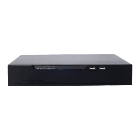
Network Video Recorder(NVR) 3 Operation Instruction User Manual Operation Instruction 3.1 Front panel Figure 3-1 shows the front panel of NVR. Table 3-1 shows the description of front panel. Figure 3-1 Front panel Table 3-1 Elements of the front panel Element Description Supports connection to a USB mouse and... - Page 17 Network Video Recorder(NVR) User Manual 3 Operation Instruction Figure 3-3 shows the rear panel of 0E-4CHNVR1TB & 0E-4CHNVR2TB and the interfaces on it. Figure 3-3 Rear panel of 0E-4CHNVR1TB & 0E-4CHNVR2TB Table 3-2 shows the description of rear panel of 0E-8CHNVR2TB, 0E-4CHNVR1TB &...
-
Page 18: Startup
Network Video Recorder(NVR) 3 Operation Instruction User Manual Table 3-3 Elements of the real panel of 0E-16CHNVR2T & 0E-16CHNVR4T Name Description PoE network PoE network interfaces interface RJ45 10 /100/1000 Mbps adaptive Ethernet interface Reset Factory reset button Line In/ Line Out Audio input/ Audio output Video output interface HD-OUT... -
Page 19: Shutdown
Network Video Recorder(NVR) User Manual 3 Operation Instruction Figure 3-4 NVR self-test When the hardware abnormality is detected, the self-test screen stays on. You can click continue or shutdown in the lower right corner of the screen. If you click continue, the NVR enters the login screen. -
Page 20: Adjusting The Screen Resolution Of The Monitor
Network Video Recorder(NVR) 3 Operation Instruction User Manual Figure 3-5 Shutdown interface Enter the correct password and click Shutdown. When authentication is successful, the shutdown successful page is displayed, then cut off the power. 3.5 Adjusting the Screen Resolution of the Monitor You need to adjust the display of the monitor in the case of incomplete or skewed display (the icon in the four corners of the screen is out of view). -
Page 21: Login
Network Video Recorder(NVR) User Manual 3 Operation Instruction Figure 3-6 Monitor Setup interface Step 2 Select a step from the Step Size dropdown list. Step: is the distance the screen moves during each adjustment. The greater the value is, the longer the distance of movement. First select a large step for rough adjustment and then select a small step for fine adjustment. -
Page 22: Changing Password
Network Video Recorder(NVR) 3 Operation Instruction User Manual Figure 3-7 Login interface of the NVR The superuser is admin and the password is also admin, both of which are case-sensitive. Change the password after logging in to the NVR for the first time. ... -
Page 23: Adding Webcams
Network Video Recorder(NVR) User Manual 3 Operation Instruction The change password page will be displayed if you don’t change the default password when you login the system for the first time. Step 2 Enter the old password, new password, and confirmation password. Step 3 Click Apply. -
Page 24: Quick Setup
Network Video Recorder(NVR) 4 Quick Setup User Manual Quick Setup Quick setup provide NVR basic information configuration, NVR network configuration, alarm configuration, disk management, time setting, IP camera search, video configuration, camera network configuration, stream configuration, and mobile detection configuration. Figure 4-1 shows the quick setup screen. - Page 25 Network Video Recorder(NVR) User Manual 4 Quick Setup The default IP address of the NVR is: 192.0.0.64. You can enable automatic IP address acquisition and set the IP address, DNS address of the NVR, and display the network connection status and speed. 4.
- Page 26 Network Video Recorder(NVR) 4 Quick Setup User Manual Figure 4-2 Camera searching page Click , the camera select interface is displayed as shown in Figure 4-3. Select the cameras you want and then click OK to complete selection of IP cameras. Figure 4-3 Camera selecting page To remove managed cameras, click in the camera list, select the cameras to...
- Page 27 Network Video Recorder(NVR) User Manual 4 Quick Setup Viewing the status of an IP camera The camera status may be Online, Offline, and Incorrect account. For an online IP camera, click to view live video. Changing the channel name Click the channel and enter a new channel name in the Name text field.
-
Page 28: Live Video
Network Video Recorder(NVR) 5 Live Video User Manual Live Video Enter your user name and password on the login interface and click Login. The Live Video interface appears, as shown in Figure 5-1. Figure 5-1 Live Video interface On the Live Video interface, drag a camera in the Cameras pane on the left to the live channel and perform the following operations: ... - Page 29 Network Video Recorder(NVR) User Manual 5 Live Video Intelligent code stream adaptation The system provides an intelligent code stream adaptation mechanism. When a video is played, the system selects a proper code stream based on the sizes and number of video windows and its own decoding capability to achieve optimal real-time surveillance effect.
- Page 30 Network Video Recorder(NVR) 5 Live Video User Manual Name Description icon becomes :Open stretch. Click to close stretch and the icon becomes :Open fluency pattern. Click to close fluency pattern and the icon becomes : The PTZ control menu appears when you click this button.
- Page 31 Network Video Recorder(NVR) User Manual 5 Live Video Figure 5-2 PTZ control menu In the PTZ control area, you can perform the following operations: Slide the slider left or right beyond the PTZ rotation keys, you can adjust the PTZ rotation speed.
- Page 32 Network Video Recorder(NVR) 5 Live Video User Manual Add, delete, and invoke preset positions. Add, delete, and invoke tracks. Add, delete, and invoke scans. Add, delete, and invoke tours. Set the idle. Set the timer. ...
-
Page 33: Video Playback
Network Video Recorder(NVR) Video Playback User Manual Video Playback 6.1 Video Playback Video playback refers to playing of videos stored in local hard disks, as shown in Figure 6-1. Figure 6-1 Local video playback Take the following steps to play a video: Step 1 Select a camera. -
Page 34: Video Backup
Network Video Recorder(NVR) 6 Video Playback User Manual axis displays videos. Reserved videos are in blue, alarm videos are in red, bookmarked videos are in yellow, and ordinary videos are in green. : Enter a time point in the Focus time field and click Then the video corresponding to the specified time is played. - Page 35 Network Video Recorder(NVR) Video Playback User Manual Figure 6-3 Backup path browse dialog box The Backup Path bar displays the selected backup path. If it is empty, select a backup path. The list below shows available backup storage devices. The NVR supports two types of backup storage device, that is, USB storage device and ESATA Disk.
- Page 36 Network Video Recorder(NVR) 6 Video Playback User Manual Figure 6-4 Video backup control bar Select channels of NVR to backup. Click Select in the video backup control bar to select a video segment. Select the video file to be backed up (the selected video segment is highlighted in blue in the display area), click and hold the left mouse button, and drag the cursor horizontally to select the video file segment to be backed up.
-
Page 37: Alarm Search
Network Video Recorder(NVR) Alarm Search User Manual Alarm Search You can search for alarm videos on the Alarm Search interface. Operation procedure Step 1 Click at the top of the interface. The Alarm Search interface appears, as shown in Figure 7-1. Step 2 Select a camera in the Cameras pane. - Page 38 Network Video Recorder(NVR) 7 Alarm Search User Manual Step 6 Play a video. Double-click an alarm video file and the video begin to play. Step 7 Back up an alarm record. Select a video and click the Backup button to back up the video to the backup folder. ----End Issue V1.0 (2018-05-11)
-
Page 39: Setting
Network Video Recorder(NVR) Setting User Manual Setting 8.1 NVR Setup 8.1.1 Device Information Click in the upper right corner and choose Setting. The NVR Setup interface appears, as shown in Figure 8-1. Figure 8-1 NVR Setup interface The Device Information pane shows the following parameters: ... -
Page 40: Device
Network Video Recorder(NVR) 8 Setting User Manual Cameras Supported Disks Supported Among the preceding parameters, only Device Name can be modified. The device information is updated automatically when the NVR is upgraded and keeps consistent with the software version of the NVR. 8.2 Device 8.2.1 Network On the Network interface, you can view the DHCP IP address (automatically obtained... - Page 41 Network Video Recorder(NVR) Setting User Manual Figure 8-2 Network interface Step 2 Set parameters on the Network interface. Table 8-1 describes the meanings of the parameters. Table 8-1 Description of network parameters Parameter Description Setting Network Ethernet interface of NVR. [Setting method] Select a value from the drop-down list box.
-
Page 42: System
Network Video Recorder(NVR) 8 Setting User Manual Parameter Description Setting DHCP IP [How to set] IP address of a camera, which is set based on actual conditions Enter an IP address in the corresponding field. [Default value] 192.0.0.64 Preferred DNS IP address of the DNS server [How to set] Server... -
Page 43: Device Port
Network Video Recorder(NVR) Setting User Manual Figure 8-3 System interface Step 2 Select Web Mode from drop-down list box. Step 3 Click ,The "Apply success" prompt is displayed. Step 4 Click OK. The setting is saved automatically. -----End 8.2.3 Device Port You must configure the HTTP port, control port and RTMP port for device route mapping in a LAN. -
Page 44: Date And Time
Network Video Recorder(NVR) 8 Setting User Manual Figure 8-4 Device Port interface Step 2 Set the parameters according to Table 8-2. Table 8-2 Device port parameters Parameter Description Setting Control Port Port used for audio and video [How to set] transfer and signaling interaction. - Page 45 Network Video Recorder(NVR) Setting User Manual Step 1 Choose Setting>NVR Setup>Device>Date and Time. The Date and Time interface appears, as shown in Figure 8-5. Table 8-3 describes the parameters. Figure 8-5 Date and Time interface Table 8-3 Date and time parameters Parameter Description Setting...
- Page 46 Network Video Recorder(NVR) 8 Setting User Manual Parameter Description Setting Daylight When the DST start time arrives, [Setting method] Savings Time the device time automatically Click the button on to goes forward one hour. When the enable Daylight savings DST end time arrives, the device time.
-
Page 47: Channel
Network Video Recorder(NVR) Setting User Manual 8.3 Channel 8.3.1 Manage Channel On the Manage Channel interface, you can add, and delete cameras. Choose Setting >NVR Setup>Channel >Manage Channel. The Manage Channel interface appears, as shown in Figure 8-6. It lists the front-end devices connected to the NVR and shows related device information. -
Page 48: Stream
Network Video Recorder(NVR) 8 Setting User Manual Figure 8-7 Camera Information interface The Camera Information pane shows the following parameters: Camera ID Camera Name Camera Type Product Name Hardware Version Software Version Camera Quantity ... - Page 49 Network Video Recorder(NVR) Setting User Manual Figure 8-8 Stream interface Step 2 Set the parameters according to Table 8-4. Table 8-4 Stream parameters Parameter Description Setting Channel ID ID of the video output channel. [Setting method] Select a value from the NOTE drop-down list box.
- Page 50 Network Video Recorder(NVR) 8 Setting User Manual Parameter Description Setting Video The video codec determines the image [Setting method] Encode quality and network bandwidth required Select a value from the Type by a video. Currently, the following drop-down list box. codec standards are supported: [Default value] ...
- Page 51 Network Video Recorder(NVR) Setting User Manual Parameter Description Setting Video The level of decoding performance of the [Setting method] Encode device. Select a value from the Level Video Encode Level of H.264 contains: drop-down list box. Low: H264 Base profile [Default value] Mid: H264 Main Profile H.264 High Profile...
-
Page 52: Network
Network Video Recorder(NVR) 8 Setting User Manual Parameter Description Setting I Frame I frames do not require other frames to [Setting method] Interval(f) decode. Select a value from the drop-down list box. A smaller I frame interval means better video quality but higher bandwidth. Bit Rate The bit rate is the number of bits [Setting method]... - Page 53 Network Video Recorder(NVR) Setting User Manual Preferred Domain Name System (DNS) server Alternate DNS server Procedure Step 1 Click Setting>NVR Setup>Channel>Network. The Network interface appears, as shown in Figure 8-9. Figure 8-9 Network interface Step 2 Set the parameters according to Table 8-5. Table 8-5 Network parameters Parameter Description...
-
Page 54: Osd
Network Video Recorder(NVR) 8 Setting User Manual Parameter Description Setting Subnet Mask Subnet mask of the network [Setting method] adapter. Enter a value manually. [Default value] Default This parameter must be set if the [Setting method] Gateway client accesses the device through Enter a value manually. - Page 55 Network Video Recorder(NVR) Setting User Manual Figure 8-10 OSD interface Step 2 Set the parameters according to Table 8-6. Table 8-6 OSD parameters Parameter Description Setting Channel ID ID of the video output channel. [Setting method] Select a value from the drop-down list box.
- Page 56 Network Video Recorder(NVR) 8 Setting User Manual Parameter Description Setting Channel ID Indicates whether to display the [Setting method] channel ID. Select“ Channel ID” from the drop-down list box and click Channel Name Indicates the channel name. [Setting method] Select “Channel Name” from the drop-down list box and click Time...
-
Page 57: Privacy Masking
Network Video Recorder(NVR) Setting User Manual Maximum 5 OSD items in the OSD field.. Click to set the OSD displayed left-aligned. Click to set the OSD display right-aligned. Select an OSD item, click move up the OSD display items, and click to move down the OSD display items. -
Page 58: Motion Alarm
Network Video Recorder(NVR) 8 Setting User Manual Step 3 Press and hold the left mouse button, and drag on the preview image to cover the part to be masked. Click the right mouse button on the preview image to clear the masked area. ... - Page 59 Network Video Recorder(NVR) Setting User Manual Step 2 Select channel ID. Step 3 Click motion alarm button to enable motion alarm. Step 4 Set motion area. 1. Click , the motion area setting interface is displayed, as shown in Figure 8-13. Figure 8-13 Motion Area interface 2.
-
Page 60: Intelligence Analyse Alarm
Network Video Recorder(NVR) 8 Setting User Manual Method 1:Click left mouse button to select any time point within 0:00-24:00 from Monday to Sunday as shown in Figure 8-14. Method 2:Hold down the left mouse button, drag and release mouse to select the deployment time within 0:00-24:00 from Monday to Sunday. -
Page 61: Video Lost Alarm
Network Video Recorder(NVR) Setting User Manual Figure 8-15 Intelligence Analyse Alarm interface Step 2 Select channel ID. Step 3 Click intelligence analyse alarm button to enable intelligence analyse alarm. Step 4 Set schedule. For details, see 8.3.7 Step 6 Set motion alarm schedule. Step 5 Check Channel Record. - Page 62 Network Video Recorder(NVR) 8 Setting User Manual Take the following steps to set video lost alarm: Step 1 Setting>NVR Setup>Channel>video lost Alarm , The video lost alarm interface is displayed, as shown in Figure 8-16. Figure 8-16 Video Lost Alarm interface ...
-
Page 63: Alarm Input
Network Video Recorder(NVR) Setting User Manual 8.3.10 Alarm Input Take the following steps to set alarm input: Step 1 Setting>NVR Setup>Channel>Alarm Input. The alarm input interface is displayed, as shown in Figure 8-17. Figure 8-17 Alarm Input interface Step 2 Select channel ID. Step 3 Select alarm I/O channel. -
Page 64: Camera Maintenance
Network Video Recorder(NVR) 8 Setting User Manual Step 11 Check Alarm Output. Select alarm output channel ID and alarm output time(s) to enable alarm output linkage. Step 12 Check Send Email to enable email linkage. Step 13 Click Apply. The message "Apply success" is displayed. Step 14 Click OK. - Page 65 Network Video Recorder(NVR) Setting User Manual Creating a layout Take the following steps to create a layout: Step 1 Choose Setting>NVR Setup> Live Video Layout. The Live Video Layout interface appears, as shown in Figure 8-19. Figure 8-19 Live Video Layout interface Step 2 Click New.
- Page 66 Network Video Recorder(NVR) 8 Setting User Manual Figure 8-20 Layout creation interface Step 4 Set the save location of the new layout by choosing Shared Layout or My Layout from the Belong To dropdown list. If the new layout is saved to Shared Layout, it can be used by all users after logging in to the NVR.
-
Page 67: Record
Network Video Recorder(NVR) Setting User Manual 8.5 Record 8.5.1 Record Policy On the Record Policy interface, you can set scheduled record, record audio, storage policy. Step 1 Choose Setting>NVR Setup>Record>Record Policy. The Record Policy interface appears, as shown in Figure 8-21. Figure 8-21 Record Policy interface Step 2 Check the box preceding the device on which scheduled recording and alarm recording need to be enabled and select the corresponding code stream for recording. - Page 68 Network Video Recorder(NVR) 8 Setting User Manual Figure 8-22 Record Policy setting interface Step 4 Set a record plan. The record plans of 24*7-hourand scheduled recording are available. If you select timed recording, set the corresponding time as follows: Click following the schedule setting.
-
Page 69: Storage
Network Video Recorder(NVR) Setting User Manual Click Ok. Step 5 Enable or disable record audio. To enable record audio, click ON. Step 6 Set a storage policy. The following storage policies are available: Overwrite in the case of full hard disks ... -
Page 70: Network Service
Network Video Recorder(NVR) 8 Setting User Manual Figure 8-24 Storage Configuration interface Before removing a hard disk from the NVR, unload the hard disk. 8.6 Network Service 8.6.1 DDNS Connect the specified camera to the Internet, and obtain the user name and password for logging into the Dynamic Domain Name System (DDNS) server. - Page 71 Network Video Recorder(NVR) Setting User Manual Figure 8-25 DDNS interface Step 2 Set the parameters according to Table 8-7. Table 8-7 DDNS parameters Parameter Description Setting DDNS Indicates whether to enable the [Setting method] DDNS service. Click the button on to enable DDNS.
-
Page 72: Pppoe
Network Video Recorder(NVR) 8 Setting User Manual Parameter Description Setting Network card Ethernet interface of NVR. [How to set] Select from drop-down list box. [Default value] LAN WAN Host Name Host name customized by a user. [Setting method] Enter a value manually. [Default value] -.wboxddns.com Step 3 Click Test DDNS. - Page 73 Network Video Recorder(NVR) Setting User Manual Figure 8-26 The PPPoE interface Step 2 Click the button on to enable PPPoE. Set the parameters according to Table 8-8. Table 8-8 PPPoE parameters Parameter Description Setting PPPoE Indicates whether to enable the [Setting method] PPPoE service.
-
Page 74: Smtp
Network Video Recorder(NVR) 8 Setting User Manual 8.6.3 SMTP If the Simple Mail Transfer Protocol (SMTP) function is enabled, the device automatically sends JPG images and alarm information to specified email addresses when an alarm is generated. Step 1 Choose Setting > NVR Setup>Network Service>SMTP. The SMTP interface is displayed, as shown in Figure 8-27. -
Page 75: Ip Filter
Network Video Recorder(NVR) Setting User Manual Parameter Description Setting Password Password of the mailbox for [Setting method] sending emails. Enter a value manually. Sender E-mail Mailbox for sending emails. [Setting method] Address Enter a value manually. Recipient_E- (Mandatory) Email address of [Setting method] mail_Address1 recipient 1. - Page 76 Network Video Recorder(NVR) 8 Setting User Manual Figure 8-28 Black and White Name interface Step 3 Select a rule type from the drop-down list box. Black list: Forbid the specified segment from connecting and accessing the NVR. White list: Allow the specified network segment connecting and accessing the NVR. Step 4 Add a rule type 1.
-
Page 77: External Device
Network Video Recorder(NVR) Setting User Manual 3. Click OK. The system saves the settings. And the name listed in the black (white) list. Select a name in the list and click to delete the name from the list. Select a name in the list and click to edit the name in the list. -
Page 78: Alarm
Network Video Recorder(NVR) 8 Setting User Manual Step 6 Click OK, the system saves the settings. 8.8 Alarm 8.8.1 Alarm Input Choose Setting>NVR Setup>Alarm>Alarm Input. For details, see 8.3.10 Alarm Input 8.8.2 .Alarm Out Step 1 Choose Setting>NVR Setup>Alarm>Alarm Out. The Alarm Out interface appears, as shown in Figure 8-31. -
Page 79: Disk Alarm
Network Video Recorder(NVR) Setting User Manual Table 8-10 Alarm out parameters Parameter Description Setting Alarm Output ID of the alarm output channel. [Setting method] Select a value from the NOTE drop-down list box. The number of alarm output [Default value] channels depends on the device model. -
Page 80: Privilege
Network Video Recorder(NVR) 8 Setting User Manual Figure 8-32 Disk Alarm interface Step 2 Click the button ON to enable disk full alarm (disk error alarm, no disk alarm) function. Step 3 Select the alarm output, then choose alarm output channel number and set the alarm out time. - Page 81 Network Video Recorder(NVR) Setting User Manual Device parameter configuration System maintenance Step 1 Choose Setting>NVR Setup>Privilege. The Privilege interface appears, as shown in Figure 8-33. Figure 8-33 Privilege interface Step 2 Add or delete a user. Adding a user 1.
- Page 82 Network Video Recorder(NVR) 8 Setting User Manual Figure 8-34 Add user interface 2. Enter a username, password and confirm password. The password should include letter, character and number. The password must be not less than 8. 3. Select a Group from the drop-down list box. 4.
- Page 83 Network Video Recorder(NVR) Setting User Manual Editing user Select a user and click , the Edit User interface is displayed, as shown in Figure 8-35. Figure 8-35 Edit user interface 7. Modify information of the user (user name, password, confirm password, group, note and manage privilege).Click OK.
-
Page 84: Device Log
Network Video Recorder(NVR) 8 Setting User Manual The Delete Group dialog box appears as shown in Figure 8-36. Figure 8-36 Confirm to delete interface 8. Click Yes. The system returns to the Groups interface and the user is deleted successfully. ... - Page 85 Network Video Recorder(NVR) Setting User Manual Figure 8-37 Alarm Log interface Query alarm information Step 1 Select the warning type from the drop-down list. Step 2 Enter the begin time and end time. Step 3 Click , the search results will display below the alarm log interface as shown in Figure 8-38.
-
Page 86: Operation Log
Network Video Recorder(NVR) 8 Setting User Manual Figure 8-38 Alarm query interface 8.10.2 Operation Log Choose Setting > NVR Setup>Device Log>Operation Log. The Operation Log interface appears, as shown in Figure 8-39. Issue V1.0 (2018-05-11) - Page 87 Network Video Recorder(NVR) Setting User Manual Figure 8-39 Operation Log interface Query operation log information Step 1 Select the log type from the drop-down list. Step 2 Enter the begin time and end time. Step 3 Click , the search results will display below the operation log interface as shown in Figure 8-40.
-
Page 88: Scheduled Reboot
Network Video Recorder(NVR) 8 Setting User Manual Figure 8-40 Operation query interface -----End 8.11 Scheduled Reboot Step 1 Choose Setting> NVR Setup>Scheduled Reboot. The Scheduled Reboot interface appears, as shown in Figure 8-41. Issue V1.0 (2018-05-11) -
Page 89: System
Network Video Recorder(NVR) Setting User Manual Figure 8-41 Scheduled Reboot interface Step 2 Click ON to enable scheduled reboot. Step 3 Add or Delete reboot schedule. Adding a reboot schedule 1. Tick Week and select the reboot time from the down-drop list box. 2. -
Page 90: Maintenance
Network Video Recorder(NVR) 8 Setting User Manual Figure 8-42 System interface Step 2 Click the button ON to enable Live Video window Tip, Login automatically, Auto Lock and window show maximize while alarm triggering. Step 3 Select wait time from the drop-down list box. Step 4 Select lock screen mode from the drop-down list box. - Page 91 Network Video Recorder(NVR) Setting User Manual If the button is disable, the IP address of camera will be reset to factory setup when the camera restores factory setup. Step 3 Click The Are you sure to restore? dialog box appears. Step 4 Click Yes, the device restore to the factory settings.
-
Page 92: Web Access
Network Video Recorder(NVR) 9 Web Access User Manual Web Access The NVR is embedded with a web server and supports mainstream browsers such as Internet Explorer, Chrome, Firefox, and Safari. Operations such as quick setup, real- time preview, video playback, alarm search, NVR setup, and camera setup can be performed through the web. -
Page 93: Live Video
Network Video Recorder(NVR) Web Access User Manual 9.2 Live Video On the Live Video interface, you can select an online camera in the left Cameras pane and view the corresponding live video. Click Live Video. The Live Video interface appears, as shown in Figure 9-2. Figure 9-2 Live Video interface 9.3 Video Playback On the Playback interface, you can search for and play videos. - Page 94 Network Video Recorder(NVR) 9 Web Access User Manual Step 4 Display videos. After a camera and date are selected, video information is displayed below the video pane. The time scale above the file axis shows the different time points of video recording.
- Page 95 Network Video Recorder(NVR) Web Access User Manual Figure 9-4 Alarm Search interface Step 2 Select a camera in the left Cameras pane. Step 3 Select an alarm type from the Type dropdown list. Step 4 Select a date. Select a date in the Date pane. Click to change months or click to change years.
- Page 96 Network Video Recorder(NVR) 9 Web Access User Manual Figure 9-5 NVR Setup interface -----End Issue V1.0 (2018-05-11)
- Page 97 Network Video Recorder(NVR) User Manual 1. Why is the NVR self-test screen frozen? Use the methods below to fix the problem: Method 1: Check whether the NVR is equipped with a hard disk. Method 2: Check whether the NVR is equipped with an unformatted hard disk. Method 3: Check whether the hard disk is damaged.
Need help?
Do you have a question about the 0E-4CHNVR2TB and is the answer not in the manual?
Questions and answers