GAL MOVFR Installation Manual
Door operator
Hide thumbs
Also See for MOVFR:
- Installation instructions manual (9 pages) ,
- How to connect (2 pages) ,
- Quick setup (2 pages)
Table of Contents
Advertisement
Advertisement
Table of Contents

Related Manuals for GAL MOVFR


Summary of Contents for GAL MOVFR
- Page 1 G.A.L. Manufacturing Corporation 50 East 153rd Street, Phone 718-292-9000 718-292-2034 Bronx, N.Y. 10451 Toll Free 877-425-3538 www.gal.com 877-425-7763 E-mail info@gal.com MOVFR DOOR OPERATOR INSTALLATION AND ADJUSTING MANUAL Doc. No. DOC-0015N Revision B (12/07)
-
Page 2: Comments
COMMENTS All G.A.L. door operators are factory adjusted and tested for the actual job requirements. When installed correctly, they may require minor adjustments to suit actual job conditions. IMPORTANT: All equipment must be installed, adjusted, tested and maintained to comply with all Federal, State, and Local codes. -
Page 3: Foreword
FOREWORD It is the intent of this manual to give the reader certain key points of information critical to the proper installation of the door operator. It is not intended to give comprehensive installation procedures nor does it cover the installation of door headers, tracks, hangers, etc. It is hoped that the procedures presented in this manual will reduce the installation and adjustment time and result in a smooth, long lasting door operation. -
Page 4: Table Of Contents
7.7- Speed profiles of the MOVFR ......................7.8- Cam setting versus distance....................32 7.9- Rotational cam setting ........................7.10- Interfacing between G.A.L. certified light curtain and the MOVFR ..........7.11- MOVFR connection diagram ......................7.12- Fault description and Fault reset...................37 7.13- Applications for the heavy input.. -
Page 5: Illustrations Of The Movfr Operators
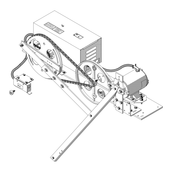
December, 2007 MOVFR OPERATORS The MOVFR door operator is our newest model. It utilizes a 1/2 HP AC motor. the controls include the AC motor, a VVVF drive and a PC board. The illustrations on this page show the three different versions available; Left Hand, Right Hand and... -
Page 6: Determining The Hand Of The Door
G.A.L. Manufacturing Corporation December, 2007 DETERMINING THE HAND OF THE DOOR G.A.L. door operators are available for right hand doors and for left hand doors. (Center parting doors use a variation of the left hand operator). to determine the hand of the door, stand in the lobby facing the elevator doors. -
Page 7: Mounting The Operator
G.A.L. Manufacturing Corporation December, 2007 MOUNTING THE OPERATOR As with all G.A.L. operators it is important to have the proper mechanical set up. Before continuing, check that doors are hung properly and glide freely with no binding. The spring closer should also be set so that the hoistway door will close fully. - Page 8 G.A.L. Manufacturing Corporation December, 2007 drive arms and connecting links are perpendicular and clear of door and track. If necessary, slide the operator base forward or backward. Proper positioning of the operator is critical to the life of the arm bearings. Bending of the drive arms will place stress on the bearings reducing their operating life.
-
Page 9: Pre-Adjustment Tip
G.A.L. Manufacturing Corporation December, 2007 PRE-ADJUSTMENT TIP BEFORE PROCEEDING TO THE ADJUSTMENT SECTIONS, READ THE FOLLOWING TIP (REFER TO FIGURE 1) Think of the drive pulley crank arm(s) and the connecting link(s) as each having its own independent role The crank arm determines the total door travel. The further the arm is away from the drive pulley, the longer the door travels. -
Page 10: Adjusting Single Speed And Two Speed Slide Doors
G.A.L. Manufacturing Corporation December, 2007 ADJUSTING THE SINGLE SPEED AND TWO SPEED SLIDE DOORS 5.1 Removing the zone locking device and the bumpers: Before adjusting the operator, remove the car door bumpers and the locking cam from the zone locking device, (see document LWZ-1). - Page 11 G.A.L. Manufacturing Corporation December, 2007 5.3 Crank arm and clutch link positions with door closed: Referring to figure 3, with the door fully closed, the crank arm should be just a few degrees above the horizontal and the clutch link about 20 degrees above the horizontal. This setting will help prevent slamming and roll back, yet still allow manual opening of the doors when the car is stopped at a landing during a power failure.
- Page 12 G.A.L. Manufacturing Corporation December, 2007 5.4 Crank arm and clutch link positions with door open: Referring to figure 4, the best door opening operation occurs when the crank arm and the connecting link are in a straight line, the clutch link is about horizontal and the car door is approximately 1/2” past the return jamb.
-
Page 13: Adjusting Center Parting Doors
G.A.L. Manufacturing Corporation December, 2007 ADJUSTING CENTER PARTING CAR DOORS 6.1 Adjusting the stop roller: Referring to figure 5A, we recommend adjusting the driven car door so that it leads the hoistway door by 1/4”. This will make the car door more closely match the hoistway door when fully open. Adjust the stop roller on the drive pulley so that the closing doors will be stopped by the roller as they meet. - Page 14 G.A.L. Manufacturing Corporation December, 2007 6.3 Crank arm and clutch link positions with doors closed: Referring to figure 6, with the doors fully closed, the connecting links should be about 1 1/2” from the horizontal centerline of the pulley. the clutch link should be at about 20 degrees above the horizontal. as shown.
- Page 15 G.A.L. Manufacturing Corporation December, 2007 6.4 Crank arm and clutch link positions with doors open: Referring to figure 7, with the doors fully open, the connecting links should be about 1 1/2” apart. the clutch link should be at about 20 degrees above the horizontal. CONNECTING LINK ASSY DRIVE PULLEY CONNECTING LINKS 1 1/2”...
-
Page 16: Single Speed 22-48 D.o. Operator Data Table Dwg. Data 21
G.A.L. Manufacturing Corporation December, 2007... -
Page 17: Two Speed 30-48 D.o. Operator Data Table Dwg. Data 22
G.A.L. Manufacturing Corporation December, 2007... -
Page 18: Center Opening 30-59 D.o. Operator Data Table Dwg. Data 23
G.A.L. Manufacturing Corporation December, 2007... -
Page 19: Electrical Adjustments
G.A.L. Manufacturing Corporation 50 East 153rd Street, Phone 718-292-9000 718-292-2034 Bronx, N.Y. 10451 Toll Free 877-425-3538 www.gal.com 877-425-7763 E-mail info@gal.com MOVFR ELECTRICAL ADJUSTMENTS Doc. No. DOC-0015N Revision B (12/07) -
Page 20: Overview
DOOR OPERATOR TYPE MOVFR 7.1 Overview: The MOVFR is a 230VAC door operator. It is controlled by a variable voltage, variable frequency (VVVF) closed loop drive. The control includes an AC ½ HP Motor, a VVVF Drive, and a PC board. It features keypad programming with digital display, door position optical cams, sequential Light Emitting Diodes (LED) for door speed positions, obstruction detection signal, and DPM Fault Monitor* signal. - Page 21 G.A.L. Manufacturing Corporation December, 2007 Making sure that all is clear before returning to AUTO mode. Use the Parameter unit to view the Alarm history. FIGURE 7.2.A B. LED pilot lights: A Red LED is provided on each of the four input boards (open, close, nudg., heavy). Heavy input is optional.
- Page 22 G.A.L. Manufacturing Corporation December, 2007 There are 16 more LED lights are provided to indicate the position of the speed cams, limit cams and modes of operation. When a cam blocks an optical sensor, the function is activated and the corresponding LED light turns on (see Figure 7.2.B.2).
-
Page 23: Preliminary Checks
G.A.L. Manufacturing Corporation December, 2007 C. Parameter unit: The Parameter unit plugs into the drive and permits changing values of pertinent parameters (see Figure 7.4 ). 7.3 Preliminary checks: This procedure is to assure that the motor turns in the correct direction, and all speed signals are in the working order. -
Page 24: The Parameter Unit
G.A.L. Manufacturing Corporation December, 2007 7.4 The parameter unit: The Parameter unit is a tool to assist users in the following tasks: - Changing speed values, acceleration, deceleration, torque, maximum closing speed, carrier frequency, and stall reverse limit. - Downloading, and Uploading Programs to and from the Drives. - Page 25 G.A.L. Manufacturing Corporation December, 2007 D. Default settings for the MOVFR drive: DEFAULT VALUE PARAMETER # STANDARD WATERPROOF CLOSING RANGE REG. HVY. REG. HVY. REG. HVY. REG. HVY. REG. HVY. MAX. CLOSE SPEED 0-30 HOLDING TORQUE 0-30 HOLDING SPEED 0-400...
- Page 26 G.A.L. Manufacturing Corporation December, 2007 E. Convenient keys: Press to check the Speed in Hz Output Frequency Example: 19Hz Press to check Input & Output Signals. Inputs: Z: (Reserved) C: Door Close O: Door Open R: Reset V: Heavy Door L: Control Bit L M: Control Bit M H: Control Bit H...
- Page 27 The total count will be 600,000,000 times. Press to View Counter 1 or Counter 2. User List. The User List includes all the Default settings for the MOVFR drive in part D. Press , Press to view all the Parameters in the User List...
-
Page 28: Parameter Adjustments
G. LED indicators: There are 7 LEDs on the Parameter Unit. DO, DC, NUD, HLD, PRG, FLT, OVT. DO=Door Open, DC=Door Close, NUD=Nudging, HLD=Holding, PRG=Programming Mode, FLT=Fault, OVT=Over Torque. These LEDs indicate the present status of the MOVFR. 7.6 Parameter adjustments: CAUTION! All equipment must be installed and adjusted to meet Federal, State, and Local Codes. - Page 29 OVER CURRENT FAULT, and turn on the FAULT LED. Recycling the Power to MOVFR or using the Reset switch on the Main Board or the Parameter Unit will Reset the Fault. However, a thorough inspection should be done before Resetting the Fault.
- Page 30 The MOVFR Drive is compliant with the CE regulation. However, if adjacent electronics, with poor EMI immunity, are affected by EMI of the MOVFR, users can lower the value of this Parameter to reduce the EMI level. The trade-off is the lower carrier frequency; the more audible noise will be...
-
Page 31: Speed Profiles Of The Movfr
G.A.L. Manufacturing Corporation December, 2007 7.7 Speed profiles of the MOVFR: A. Closing Cycle: Pr.# 4 DECEL Pr.# 8 ACCEL. Pr.# 7 Pr.# 8 HSC ZONE FSC ZONE DCL & HOLDING Pr.# 2 CLOSE CYCLE GRAPH FULL OPEN TO FULL CLOSE B. -
Page 32: Cam Setting Versus Distance
G.A.L. Manufacturing Corporation December, 2007 7.8 Cam setting versus Distance: CLOSING DIRECTION SPEED 1/2 inch Last before Last DISTANCE Gate Until the door reaches 4 inches from the final close inch Switch is inches activated CAM 4 CAM 5 CAM 6 OPENING DIRECTION SPEED Last... -
Page 33: Rotational Cam Setting
G.A.L. Manufacturing Corporation December, 2007 7.9 Rotational cam setting:... -
Page 34: Interfacing Between G.a.l. Certified Light Curtain And The Movfr
• Tri-Tronics B. Operation: When obstruction on the edges occurs, the reopen LED on the MOVFR will turn on and the reopen relay will be activated. The reopen contacts will send reopen signal to the main controller and wait for... - Page 35 C. Wiring diagram: TRI-TRONICS (Leading Edge) Insert enable chip Make sure that the reopen contact DPPC-0001N (U5) of the MOVFR is connected to the into the socket. main controller. Make sure the red stripe is positioned in pin 1 as shown.
-
Page 36: Movfr Connection Diagram
G.A.L. Manufacturing Corporation December, 2007 7.11 MOVFR connection diagram: INFRARED LIGHT CURTAIN CONNECTIONS WARNING: WARNING: 50 East 153rd Street Bronx, N.Y. 10451 Tel. 718 292 9000 Fax 718 292 2034... -
Page 37: Fault Description And Fault Reset
G.A.L. Manufacturing Corporation December, 2007 7.12 Fault description and Fault reset: F01 HW Over Current The AC drive detects an abnormal increase in current. The maximum allowable hardware current is 300% (9A). When the drive output has exceeded this limit, the “F01” fault code will display on the parameter unit display. - Page 38 G.A.L. Manufacturing Corporation December, 2007 Set Par. 112 for the Number of Retries. Default Value: 6 Range: 0 Increment: 1 After fault occurs, the AC drive can be reset/restarted automatically up to 10 times. Setting this parameter to 0 will disable the reset/restart operation after any fault has occurred. Set Par.113 for the Retry Waiting Time.
-
Page 39: Applications For The Heavy Input
G.A.L. Manufacturing Corporation December, 2007 7.13 Applications for the heavy input: The door operator may operate two different hoist-way doors, one door is heavier than the other, in one elevator. As a result, the setting of Torque, and Speed of one door may not be applicable for the other door. - Page 40 G.A.L. Manufacturing Corporation December, 2007 Pr.15 Heavy Final Speed Close (FSC) Unit: 0.1 Hz Default: 5.0 Hz Range: 0 ~ 400.0 Hz Pr.16 Heavy Door Nudging Speed Unit: 0.1 Hz Default: 9.0 Hz Range: 0 ~ 400.0 Hz Pr.17 Heavy Door Close Acceleration Time Unit: 0.1 Sec Default: 6.0 Range: 0 ~ 320.0 Sec...
- Page 41 G.A.L. Manufacturing Corporation December, 2007 Pr.34 Heavy Door Medium Speed Open (MSO) Unit: 0.1 Hz Default: 20.0 Hz Range: 0 ~ 400.0 Hz Pr.35 Heavy Door Final Speed Open (FSO) Unit: 0.1 Hz Default: 5.0 Hz Range: 0 ~ 400.0 Hz Pr.36 Heavy Door Open Acceleration Time Unit: 0.1 Sec Default: 4.0 Sec...
- Page 42 G.A.L. Manufacturing Corporation December, 2007 Pr.39 Heavy Door Open Torque (Second V/F (base frequency) Unit: 0.1 Hz Default: 80.0 Hz Range: 0 ~ 400 Hz Increase the setting when motor torque in low speed range is insufficient. 100 % Pr.57 Pr.1 Pr.11 Setting range...
-
Page 43: Parameters List
G.A.L. Manufacturing Corporation December, 2007 7.14 Parameters list: Pr.0 Max. Close Speed (Close Speed detection) Unit: 0.1 Hz Default: 30.0 Hz Range: 0 ~ 400.0 Hz The output frequency detection signal is on when the output frequency reaches or exceeds the setting value. - Page 44 G.A.L. Manufacturing Corporation December, 2007 Pr.8 Close Deceleration Time Unit: 0.1 Sec Default: 10.0 Range: 0 ~ 320.0 Sec The Deceleration time is used to determine the time required for the AC drive to decelerate from the reference frequency (Pr.50) down to 0 Hz. Pr.9 Stall Reverse Force (output current detection level) Unit: (0.1 %)
- Page 45 G.A.L. Manufacturing Corporation December, 2007 Pr.14 Heavy Door High Speed Close (HSC) Unit: 0.1 Hz Default: 19.0 Hz Range: 0 ~ 400.0 Hz Pr.15 Final Speed Close (FSC) Unit: 0.1 Hz Default: 5.0 Hz Range: 0 ~ 400.0 Hz Pr.16 Heavy Door Nudging Speed Unit: 0.1 Hz Default: 9.0 Hz Range: 0 ~ 400.0 Hz...
- Page 46 G.A.L. Manufacturing Corporation December, 2007 Pr.22 Slow Start Open (SSO) Unit: 0.1 Hz Default: 5.0 Hz Range: 0 ~ 400.0 Hz 100 % Pr.57 Pr.23 High Speed Open (HSO) Unit: 0.1 Hz Default: 45.0 Hz Range: 0 ~ 400.0 Hz Pr.24 Medium Speed Open (MSO) Unit: 0.1 Hz Default: 20.0 Hz...
- Page 47 G.A.L. Manufacturing Corporation December, 2007 Pr.31 Heavy Door Quick Stop on Reverse Unit: 0.1 A Default: 2.0A Range: 0~180 %rated This parameter determines the level of the DC braking Current output to the motor during stopping. Pr.32 Heavy Door Slow Start Open (SSO) Unit: 0.1 Hz Default: 5.0 Hz Range: 0 ~ 400.0 Hz...
- Page 48 G.A.L. Manufacturing Corporation December, 2007 Pr.39 Heavy Door Open Torque (Second V/F (base frequency) Unit: 0.1 Hz Default: 80.0 Hz Range: 0 ~ 400 Hz Increase the setting when motor torque in low speed range is insufficient. Pr.40 DC Injection Brake Operation Frequency Unit: 0.1 Hz Default: 60 Hz Range: 0 ~ 400.0 Hz...
- Page 49 G.A.L. Manufacturing Corporation December, 2007 Pr.51 Max. Carrier Frequency Carrier frequency for the PWM output waveform Unit: 0.1k Hz Default: 11.0k Hz Range: 2.0 ~ 15.0kHz This parameter determines the maximum carrier frequency of the AC drive. Electromagnetic Noise, Carrier Frequency Acoustic Noise Heat Dissipation Leakage Current...
-
Page 50: How To Replace The Drive
G.A.L. Manufacturing Corporation December, 2007 Pr.113 Retry Waiting Time Unit: 0.1 Sec Default: 2.5 Sec Range: 0 ~ 120.0 Sec Sets the time between restart attempts when Auto Restart Tries is set to a value other than zero. Pr.114 Retry Selection Unit: 1 Default: 1023 Range: 0 ~ 1023... - Page 51 Copyright © 2004, G.A.L. Manufacturing Corporation All rights reserved. No part of this document may be reproduced in any form, machine or natural, without the express written consent of G.A.L Manufacturing Corporation.
Need help?
Do you have a question about the MOVFR and is the answer not in the manual?
Questions and answers
What’s this