Advertisement
Quick Links
Advertisement

Related Manuals for Kewtech KTD40


Summary of Contents for Kewtech KTD40
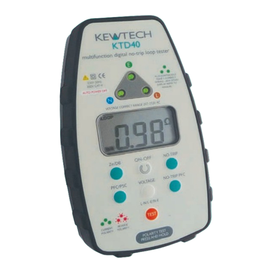
- Page 1 KTD40 Multifunction Digital Loop Impedance Tester User Manual www.kewtechcorp.com...
-
Page 2: Operation Overview
Live (Phase) The sockets will all work and neutral and earth/neutral to Line (Phase). The sockets will all work and conventional loop conventional loop testers will show and test that everything is correct despite testers will show and test that everything is correct despite this very dangerous wiring Before using your KTD40 please read these instructions; in particular note the safety this very dangerous wiring condition. condition. issues that follow:... - Page 3 It is the variation in power factor that makes the TLI measurement of your KTD40 so fused test lead set as it would be likely to give incorrect results. much more accurate than older loop testing techniques. (Because of this there may well be variations in readings compared to ordinary loop testers or the no-trip function of this Lead configuration for No-trip testing tester, particularly when the measurement is made near to the main supply transformer). This is the default mode that the KTD40 will start in when turned on. This mode is most The KTD40 also has a No-trip test mode that is guaranteed not to trip a 30mA or higher useful for testing at socket outlets, luminaires, wiring terminals, etc. in installations rated RCD providing that the circuit is otherwise healthy. where the circuit under test may be protected by an RCD. No-trip vs High current testing In No-trip mode the tester can be used with the mains lead when testing at 13A socket outlets, or the distribution board lead set for testing at other points in the circuit.
- Page 4 Test lead configuration Operation – a Detailed View of the KTD40 Lead configuration for High Current 2-wire testing with TLI feature The TLI (True Loop Impedence) function is intended for use at distribution boards and similar points where you are measuring on the supply side of any Switch/RCD gear. The TLI measurement function is selected by pressing button 9 labelled ‘Ze/DB’. This function uses the maximum high current of the tester and requires the use of the distribution board lead set configured in 2-wire mode. Do not use this function with the 2 Three LEDs show mains lead or the distribution lead set in 3-wire mode. socket wiring status To arrange the test leads in 2-wire mode pull the blue prod off the blue test lead and plug the exposed 4mm connector into the back of the green connector as shown below. You will now have the Earth and Neutral leads connected together ready for connection to the Earth or Neutral conductor to be tested. 4 LCD - default L-N voltage measurement...
- Page 5 Overview of the Display Loop-PFC/PSC Testing Power ON/OFF – Pressing this button turns the KTD40 on and pressing again turns the unit off. Intelligent auto power-off occurs after 3 minutes of inactivity, but for safety the instrument stays powered if it is displaying a socket wiring fault. LOOPPFC – PSC HANDSFREE When the KTD40 is first connected to a live socket it will automatically test NO-TRIPH WAIT the socket wiring to establish that the circuit wires have been connected to the correct terminals on the back of the socket. If all three LEDs light GREEN and no Ω sound is emitted the wiring status is correct and you can proceed to the incoming supply polarity test (step 3).
-
Page 6: Specifications
Over Voltage Protection Note: In 2-wire mode the voltage displayed will be that measured across the 2 conductors that the test leads are connected to. The display will show this as L-N 440V AC No damage – complete recovery regardless of whether they are connected across L-N or L-E. Power 4 × AA batteries (not included) HANDSFREE testing in High current 2-wire mode. Battery life (BS EN 61557) > 10,000 test (or shelf life of batteries installed) This function is particularly useful for testing at distribution boards and is activated by pressing the test button before connecting to the mains supply. The KTD40 Environmental will then automatically conduct a Loop test upon connection to the live supply and display the result. The supply voltage can be recalled by pressing the Voltage Operating Temperature Range 0°C to 40°C button and the PFC/PSC result can be recalled by pressing the No-trip PFC button. Storage Temperature Range –10°C to +60°C PFC/PSC Prospective Fault Current/Prospective Short Circuit Current. Pushing this button divides the above TLI (True Loop Impedance) result into the voltage Operating Humidity 93% RH @ 40°C... - Page 7 Faulty L / N miswire Warble No Mains None Above is the indication given when touching the touch pad. LEDs will flash to indicate fault condition NC = No Connection Kewtech Corporation Limited Midas House, Unit 2b, Stones Courtyard, High Street, Chesham, Bucks HP5 1DE T: 01494 792 212 F: 01494 791 826 E: sales@kewtechcorp.com www.kewtechcorp.com...
Need help?
Do you have a question about the KTD40 and is the answer not in the manual?
Questions and answers