Table of Contents
Advertisement
Advertisement
Table of Contents

Related Manuals for Kewtech KT64


Summary of Contents for Kewtech KT64
-
Page 2: Table Of Contents
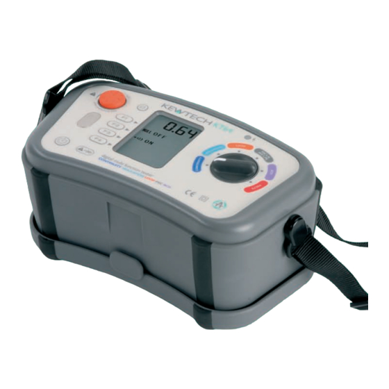
Contents 1. Safe Testing ...…………………………………………………….….……. 1 2. Instruments Layout ..………………………………………………..…….. 3 3. Accessories ……………………………………………………………….. 4 4. Features .…………………………………………………………………… 4 5. Specification .………………………………………………………………. 6 5.1 Measurement Specification ..………………………………………… 6 5.2 Operating error ..……………………………………………….……. 9 5.3 General Specification ..….………………………………………….. 10 5.4 Applied standards .………………………………………………….. 11 5.5 List of Display Message .……………………………………………... - Page 3 The KT 64 incorporates Anti Trip Technology (ATT) which electronically bypasses RCDs when performing loop impedance tests. This saves time and money by not having to take the RCD out of the circuit during testing and is a safer procedure to follow. With the ATT function enabled , a test of 15mA or less is applied between line &...
-
Page 4: Safe Testing
For safety reasons only use accessories (test leads, probes, fuses, cases, etc) designed to be used with this instrument and recommended by Kewtech. The use of other accessories is prohibited as they are unlikely to have the correct safety features. - Page 5 11 Kewtech recommends the use of fused test leads particularly when Safe Testing measuring voltages in high energy circuits. Where assessments show that the risk is significant, then the use of fuse test leads constructed in accordance with the HSE Guidance Note GS38 should be used. The test accessories supplied with this instrument for loop impedance and RCD tests are all fused.
-
Page 6: Instruments Layout
2 Instrument layout Fig. 1 Input Terminal Fig. 2 Name Operation (1) Back Light Button S w i t c h e s o n / o f f t h e B a c k l i g h t o f t h e Display(LCD) (2) Test Button Starts measurements. -
Page 7: Accessories
Distribution Board fused test lead (ACC064) (Fuse: 10A/600V fast acting ceramic) Fig. 5 Test Lead Carry pouch Carrying Bag The KT64 Multi-Function tester performs six functions in one instrument. 4 Features 1 Continuity tester 2 Insulation resistance tester 3 Loop impedance tester... - Page 8 Features Continuity and insulation resistance functions have the following features: Live circuit warning “Live Circuit” warning on the display. Continuity Null Allows automatic subtraction of test lead resistance from continuity measurements. Continuity 2Ω Buzzer Buzzer sounds at 2Ω or less at Continuity function.
-
Page 9: Specification
ALL testing functions have the following Touch Pad Gives an alert, when touching the Touch Pad, while the PE terminal is connected to Line by mistake. Auto power off Automatically switches the instrument off after a period of approximately 10 minutes. The Auto power off mode can only be cancelled by switching the instrument on again. - Page 10 Specification Loop Impedance Nominal Test Current at Rated Function 0Ω External Loop: Range Accuracy Voltage Magnitude/Duration(*1) 20Ω: 6A/20ms 100~260V 20/200/2000Ω ±(3%rdg+4dgt) *2 L-PE 200Ω: 2A/20ms 50/60Hz Auto-Ranging ±(3%rdg+8dgt) *3 2000Ω: 15mA/360ms 20/200/2000Ω L-PE 100~260V L-N: 6A/40ms ±(3%rdg+6dgt) *2 Auto-Ranging (ATT) 50/60Hz N-PE: 10mA/approx.
- Page 11 Specification Accuracy Function Rated Voltage Trip Current Trip Time AC Type A Type X1/2 -8%~-2% -10%~0% 230V+10%-15% +2%~+8% 0%~+10% ±(1%rdg+3dgt) +2%~+8% 0%~+10% 50/60Hz Ramp ( ±4% ± 10% Depending on the accuracy at each function. Measurement sequence: Auto X1/2 0°→X1/2 180°→X1 0°→X1 180°→X5 0°→X5 180° Measurements with x5 are not carried out for RCDs with nominal current of 100mA or more.
-
Page 12: Operating Error
Specification Possible number of tests with fresh batteries. Continuity :Approx. 2000 times min. at load 1Ω Insulation Resistance :Approx. 1000 times min. at load 1MΩ (1000V) LOOP/PFC/PSC :Approx. 1000 times min. (ATT) :Approx. 2000 times min. (G-AC X1 30mA) Reference Conditions Ambient temperature 23±5℃... -
Page 13: General Specification
RCD(EN61557-6) Specification Function Operating error of trip current X1/2 -10%~0% X1, X5 0%~+10% Ramp -10%~+10% The influencing variations used for calculating the operating error are denoted as follows; Temperature : 0 ℃ and 35 ℃ Earth electrode Resistance (shall not exceed below) : Earth electrode resistance (Ω... -
Page 14: Applied Standards
Specification Display Dot Matrix LCD 160(W) X 240(H) pixels. Overload protection The continuity test circuit is protected by a 0.5A/600V fast acting (HRC) ceramic fuse mounted in the battery compartment, where a spare fuse is also stored. The insulation resistance test circuit is protected by a resistor against 1000 V AC for 10 seconds. -
Page 15: List Of Display Message
5.5 List of Display Message Specification Low battery warning Temperature monitor for internal resistance, available at Loop, PSC/PFC & RCD function. Further measurements are suspended until the “ ” symbol disappears. Measuring Measurements in progress Live Circuit Live circuit warning (Continuity / Insulation Function) PE Hi V Caution : Presence of 100V or more at PE terminal, appears when touching the Touch Pad... -
Page 16: Configuration
▲ Back Light・・・・・・ Selects Backlight ON / OFF. When ON is selected, the Backlight automatically turns on at powering on the instrument. Setting method 1. Press the Config Button (F4) when powering on KT64. (Fig.6) Fig. 6 2. Then, Configuration Screen (Fig.7) is displayed. Fig. 7 3. -
Page 17: Continuity(Resistance) Tests
Fig. 8 Proceed as follows:- 1 Select the continuity test by rotating the Rotary switch. 2 Insert the Test Leads to the L and PE terminal on KT64 respectively as shown in Fig.9. L terminal Brown cord of ACC064, or... - Page 18 Continuity Fig. 10 4 Operate the Continuity Null (F1) button, this will null out the lead resistance and the indicated reading should go to zero. 5 Release the test button. Press the test button and ensure the display reads zero before proceeding. While using the Continuity null function, “NULL ”...
-
Page 19: Buzzer
Continuity Fig. 11 7.2 2Ω Buzzer ( ) function Use F2 Button to enable / disable 2Ω Buzzer. Buzzer sounds when measured resistance is 2Ω or less while this function is enabled. Buzzer does not sound if it is disabled. 8 Insulation Warning: Ensure that circuits to be tested are not live. -
Page 20: Capacitive Current
This charge must be removed from the system at the end of the test, a function which is automatically performed by the KT64. If an alternating voltage is applied between the conductors, the system continuously charges and discharges as the applied voltage alternates, so that there is a continuous alternating leakage current flowing to the system. -
Page 21: Surface Leakage Current
8.1.4 Surface Leakage Current Insulation Where insulation is removed, for the connection of conductors and so on, current will flow across the surfaces of the insulation between the bare conductors. The amount of leakage current depends on the condition of the surfaces of the insulation between the conductors. -
Page 22: Damage To Voltage Sensitive Equipment
The system is charged to the full test voltage, and will be dangerous if left with this charge. The KT64 provides an automatic path for discharging current as soon as the test button is released to ensure that the circuit under test is safely discharged. -
Page 23: Insulation Resistance Measurement
The KT64 has three selectable test voltages of 250V, 500V and 1000V DC. 1. Select INSULATION function with the Rotary switch. 2. Press the VOLT Switch (F4) and select desirable voltage range. 3. Insert the Test Leads to the L and PE terminal on KT64 respectively as shown in Fig.16. L terminal... - Page 24 Insulation Fig. 17 4 If the “Live Circuit” warning will be displayed on the LCD and/or the buzzer sounds, do not press the test button but disconnect the instrument from the circuit. Make the circuit dead before proceeding. Fig. 18 5 Press the test button, the display will show the insulation resistance of the circuit or the appliance to which the instrument is connected.
-
Page 25: Loop/Psc/Pfc Test
Every circuit must be tested to ensure that the earth fault loop impedance value does not exceed that specified or appropriate for the over- current protective device installed in the circuit. The KT64 takes a current from the supply and measures the difference between the unloaded and loaded supply voltages. - Page 26 LOOP/PSC/PFC Fig. 19 For TN systems the earth fault loop impedance is the sum of the following impedances. ▲ Impedance of the power transformer secondary winding. ▲ Impedance of the phase conductor from the power transformer to the location of the fault. ▲...
- Page 27 When the protective device is a residual device (RCD), Ia is the rated residual LOOP/PSC/PFC operating current IΔn. For example in a TT system protected by an RCD the maximum RA values are as follows: Rated residual operating 1000 current IΔn mA Ra (at 50V) Ω...
- Page 28 LOOP/PSC/PFC Note: ▲When the protective device is a residual current device(RCD), Ia is the rated residual operating current IΔn. For instance in a TN system with a nominal mains voltage of Uo = 230V protected by type gG fuses the Ia and maximum Zs values could be: Rating Disconnecting Time 5s Disconnecting Time 0.4s...
-
Page 29: Principles Of Measurement Of Line Impedance And Psc
LOOP/PSC/PFC Fig. 23 The maximum value of Zs for this example is 2.10Ω (16 amp gG fuse, 0.4 seconds). The loop tester reads 1.14Ω and consequently the condition Zs ≤ Uo/Ia is met. 9.2 Principles of the measurement of line impedance and PSC The method for measuring Line –... - Page 30 LOOP/PSC/PFC Fig.24 Connection for Line – Neutral measurement Fig.25 Connection for Line – Neutral measurement (using an outlet) Fig.26 Connection for Line – Line measurement...
-
Page 31: Operating Instructions For Loop And Psc/Pfc
1. Preparation Always inspect your test instrument and lead accessories for abnormality or damage: If abnormal conditions exist DO NOT PROCEED WITH TESTING. Have the instrument checked by Kewtech. Operation of Function Switch LOOP Switches measurement mode: L-PE or L-N/L-L ATT setting (on or off) Fig. - Page 32 LOOP/PSC/PFC Fig. 30 4 Pressing the ATT switch (F2) disables ATT mode. Then “ATT OFF” is displayed on the LCD. ▲ ATT mode enables a measurement without tripping the RCDs with the rated residual current of 30mA or more. ▲ Measurement in ATT mode requires longer time than that is required for the other measurements (approx.
-
Page 33: Measurement Of Loop And Psc/Pfc
2. Wiring Check LOOP/PSC/PFC After the connection, ensure that the symbols for Wiring check on the LCD are in the status indicated in Fig.29 before pressing the test button. If the status of the symbols for Wiring check differ from Fig.29 or symbol is indicated on the LCD, DO NOT PROCEED AS THERE IS INCORRECT WIRING. -
Page 34: Rcd Tests
LOOP/PSC/PFC c. Measurement between LINE-LINE Connect the distribution board lead ACC064 to the instrument. Press the Mode Switch(F1) and select L-N/L-L or PSC. Connect the blue N lead of the ACC064 to the line of the distribution board, the brown L lead to another line of the distribution board. (See Fig.26) Carry out the initial checks Press the test button. - Page 35 ▲ Tripping time tΔ is the time needed by the RCD to trip at a rated residual operating current of IΔn. The standard values of tripping time are defined by IEC 61009 (EN61009) and IEC 61008 (EN 61008) and are listed in the table below for IΔn and 5IΔn.
-
Page 36: Operating Instructions For Rcd
1. Preparation Always inspect your test instrument and lead accessories for abnormality or damage: If abnormal conditions exist DO NOT PROCEED WITH TESTING. Have the instrument checked by Kewtech. Operation of Function Switch Measurement mode setting (X1/2, X1, X5, Ramp, Auto) IΔn setting... -
Page 37: Rcd Measurement
2. Wiring Check 1. Insert the Test Lead into the instrument. (Fig.34) Fig. 34 2. Connect the test leads to the circuit to be tested. (Fig.31, 32) 3. After the connection, ensure that the symbols for Wiring check on the LCD are in the status indicated in Fig.34 before pressing the test button. - Page 38 1) Press F1 to select Auto 2) Press F2 & F3 to select IΔn & RCD type 3) Press the Test button. The KT64 will automatically conduct the sequence as above. When the RCD trips each time reset it. 4) Return to the tester and the results will be displayed ▲...
-
Page 39: Volts
1. Operate the Power button and turn on the instrument. Turn the rotary 11 Volts switch and select the VOLTS function. 2. Insert the Test Leads into the instrument. (Fig.35) Fig. 35 3. Voltage value and frequency will be displayed on the LCD when applying AC voltage. -
Page 40: Battery Replacement
PSC/PFC and RCD modes, it may be that the protective fuses fitted on the printed circuit board have blown. If you suspect that the fuses have failed, return the instrument to Kewtech for service - do not attempt to replace the fuses yourself. -
Page 41: Servicing And Calibration
If this tester should fail to operate correctly, return it to Kewtech marked for 17 Servicing the attention of the Service Department, stating exact nature of fault. Make sure that: Calibration a. operating instructions have been followed b. leads have been inspected c. -
Page 42: Case And Strap Assembly
1. Attach the Buckle to the KT64 as shown in Fig.37. Match the hole of the Buckle and the protrusion at the side face of KT64, and slide it upwards. - Page 43 Kewtech Corporation Ltd. Midas House, Unit 2b Stones Courtyard High Street, Chesham Buckinghamshire HP5 IDE www.kewtechcorp.com...
- Page 44 92-1885A 06-11...
Need help?
Do you have a question about the KT64 and is the answer not in the manual?
Questions and answers