Sign In
Upload
Download
Table of Contents
Contents
Add to my manuals
Delete from my manuals
Share
URL of this page:
HTML Link:
Bookmark this page
Add
Manual will be automatically added to "My Manuals"
Print this page
×
Bookmark added
×
Added to my manuals
Manuals
Brands
NIFTYLIFT Manuals
Lifting Systems
HR15
Operating/safety instructions manual
NIFTYLIFT HR15 Operating/Safety Instructions Manual
Height rider series; 2x4 series; 4x4 series heightrider
Hide thumbs
1
2
Table Of Contents
3
4
5
6
7
8
9
10
11
12
13
14
15
16
17
18
19
20
21
22
23
24
25
26
27
28
29
30
31
32
33
34
35
36
37
38
39
40
41
42
page
of
42
Go
/
42
Contents
Table of Contents
Bookmarks
Table of Contents
Table of Contents
1 Introduction and General Information Page
Foreword
Severity of Hazards
Scope
Introducing the Height Rider Self-Propelled (Sp) Series
General Specification
Identification
Identification
2 Safety
Mandatory Precautions
Environmental Limitations
Noise & Vibration
3 Preparation and Inspection
Unpacking
Preparation for Use
Pre-Operational Safety Check Schedules
Placard, Decals and Installation
Placard, Decals and Installation
Torque Requirements
4 Operation
Control Circuit Components
Ground Control Operation
Platform Control Operation
Driving Controls
Cage Weigh System
Batteries and Charging
Transporting, Craneage, Storage and Setting to Work
5 Emergency Controls
General
Emergency Procedures - Incapacitated Operator
Emergency Procedures - Machine Failure
Boom Controls
Drive Controls
Towing
Incident Notification
6 Responsibilities
Changes in Ownership
Manual of Responsibilities (USA Only)
Inspection/ Service Check List
Towing
Advertisement
Quick Links
1
General Specification
2
Control Circuit Components
3
Ground Control Operation
4
Platform Control Operation
5
Driving Controls
6
Batteries and Charging
7
Emergency Procedures - Machine Failure
Download this manual
Heightrider
Operating & Safety Instructions
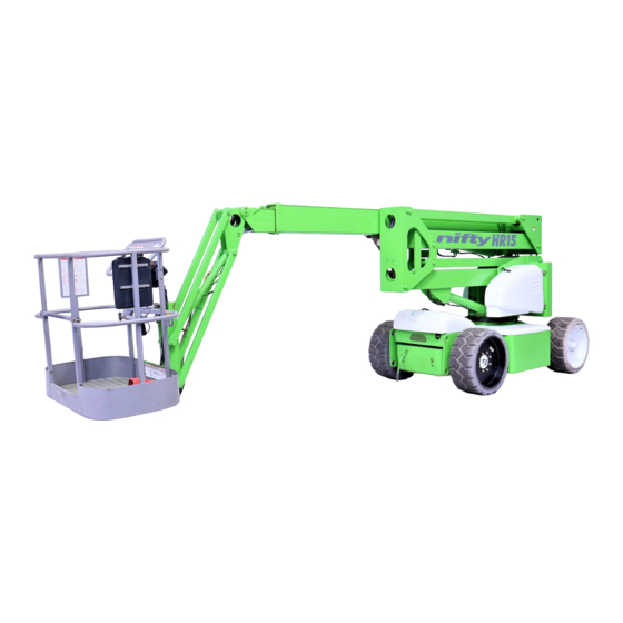
MODEL HR15 (SP45) & HR17 (SP50)
(2x4 & 4x4) SERIES
Manufactured by:
Niftylift Limited
Fingle Drive
Stonebridge
Milton Keynes
MK13 0ER
England
www.niftylift.com
e-mail: info@niftylift.com
Tel: +44 (0)1908 223456
Fax: +44 (0)1908 312733
Table of
Contents
Previous
Page
Next
Page
1
2
3
4
5
Advertisement
Table of Contents
Need help?
Do you have a question about the HR15 and is the answer not in the manual?
Ask a question
Questions and answers
Related Manuals for NIFTYLIFT HR15
Lifting Systems niftylift HR17 Operating/Safety Instructions Manual
Height rider series; 2x4 series; 4x4 series heightrider (42 pages)
Lifting Systems niftylift HR 10 Operating & Safety Manual
Height rider standard and narrow width self propelled s.p (32 pages)
Lifting Systems NIFTYLIFT nifty HR15N (SP45N) Series Operating/Safety Instructions Manual
(46 pages)
Lifting Systems NIFTYLIFT nifty HR17N (SP50N) Series Operating/Safety Instructions Manual
(46 pages)
Lifting Systems niftylift SP45 Operating/Safety Instructions Manual
Height rider series; 2x4 series; 4x4 series heightrider (42 pages)
Lifting Systems niftylift SP50 Operating/Safety Instructions Manual
Height rider series; 2x4 series; 4x4 series heightrider (42 pages)
Lifting Systems NIFTYLIFT 120 Series Operating And Safety Manual
Trailer mounted (34 pages)
Lifting Systems Niftylift SD210 Series Operating/Safety Instructions Manual
(46 pages)
Lifting Systems NIFTYLIFT SD34T Series Operating/Safety Instructions Manual
(41 pages)
Lifting Systems Niftylift SD64 Series Operating/Safety Instructions Manual
(46 pages)
This manual is also suitable for:
Sp45
Sp50
Hr17
Table of Contents
Save PDF
Print
Rename the bookmark
Delete bookmark?
Delete from my manuals?
Login
Sign In
OR
Sign in with Facebook
Sign in with Google
Upload manual
Upload from disk
Upload from URL


Need help?
Do you have a question about the HR15 and is the answer not in the manual?
Questions and answers