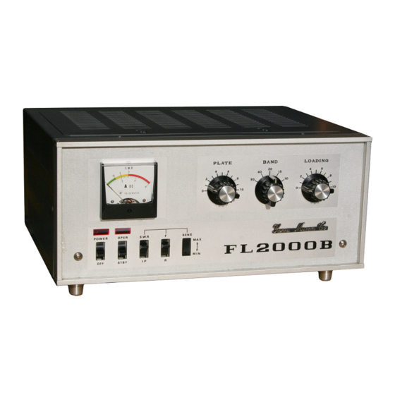
Summary of Contents for Yaesu FL-2000B
- Page 1 INSTRUCTION MANUAL FL-2000B YAESU MUSEN CO., LTD. TOKYO JAPAN Downloaded by Amateur Radio Directory...
-
Page 2: Linear Amplifier
An internal changeover relay feeds the antenna to the exciter for barefoot operation when the FL-2000B is turned off or is on standby condition. A built-in SWR bridge measures SWR on by barefoot and linear operations. The built-in solid state power supply requires no warm-up period and provides excellent voltage regulation. -
Page 3: Specifications
: Plate capacitor in tank circuit. Downloaded by INSTALLATION Amateur Radio Directory The FL-2000B has been designed incorporating two safety locks to prevent dangerous high voltage shock. However, extreme care is recommended when servicing inside the cabinet - 2 –... -
Page 4: Power Requirement
In general, care should be taken to insure that enough space is allowed around the amplifier cabinet to permit adequate air circulation within the linear amplifier. Do not cover the top of the FL-2000B with books, papers or other equipment. Do not insert anything under the bottom of the FL-2000B or overheating may result. - Page 5 It is recommended that the FL-2000B is operated from its own 220 volt 10 amp or greater circuit. If 117 or 100 volts is all that is available, it should be fused for 20 Amps, circuit conductors should be larger than #10 and no other equipment should be operated from this circuit.
-
Page 6: Antenna Requirement
FL-2000B is 50 ohms. When the impedance of the antenna used is far from this value, it is recommended that an antenna matching network be used which will allow the FL-2000B to work into its nominal 50 ohm load for maximum power transfer into the antenna. -
Page 7: Operation
Relay Control RY and E terminal on the rear of the FL-2000B are provided for connection to the exciter relay circuit which is normally open, and which closes on transmit and thus keys the FL-2000B at the same time. E terminal should be connected to ground for exciters whose relay contact connects to ground on transmit. - Page 8 BAND PLATE LOADING Turn the power switch of FL-2000B on and wait for a few seconds for tube warm up. Turn OPER switch onto "OPER" position. Turn on the exciter and increase the exciter output while not exceeding 0.2 Amps plate current and tune the-plate control for dip in the plate current.
-
Page 9: Theory Of Operation
THEORY OF OPERATION The FL-2000B is designed to use two 572B/T160 zero bias triodes in a class B grounded grid configuration. The RF driving power delivered to the input is applied to the tube filaments through a changeover relay and a pi-network on each band which is selected by the input switch S2a. - Page 10 After removing six screws on the front end and two in the bottom of the cabinet, the cabinet can be slid out backwards from the chassis and panel assembly. Tube Replacement If it becomes necessary to replace the tubes in the FL-2000B, the same manufacturer brand should be used. Trouble Shooting During long periods of operation, it is quite possible that some problem will arise which cannot be cured by tube substitution.
- Page 11 With the exciter tuned up on CW in the middle of the band to be tuned, turn on the FL-2000B. The amplifier now works without plate voltage. Extreme care should be taken, because there is high voltage AC on the secondary terminals of the high voltage transformer.
- Page 12 Downloaded by Amateur Radio Directory...
- Page 13 Downloaded by Amateur Radio Directory...
- Page 15 Downloaded by Amateur Radio Directory...
- Page 17 Downloaded by Amateur Radio Directory...
- Page 18 Downloaded by Amateur Radio Directory...
- Page 19 Downloaded by Amateur Radio Directory...
- Page 20 Downloaded by Amateur Radio Directory...


Need help?
Do you have a question about the FL-2000B and is the answer not in the manual?
Questions and answers