Yaesu FL-2100Z Instruction Manual
Hide thumbs
Also See for FL-2100Z:
- Instruction manual (16 pages) ,
- Instruction manual (15 pages) ,
- Instruction manual (16 pages)
Advertisement
Quick Links
Advertisement

Related Manuals for Yaesu FL-2100Z


Summary of Contents for Yaesu FL-2100Z
- Page 1 INSTRUCTION MANUAL\ FL·2100Z YAESU MUSEN CO., LTD. · TOKYO JAPAN...
- Page 2 A unique safety feature incorporated in the design of the FL-2100Z is a momentary bias delay circuit, which protects the tank circuitry from damage by delaying the activation of the final tubes until the T /R relay is firmly seated.
-
Page 4: Front Panel Controls And Switches
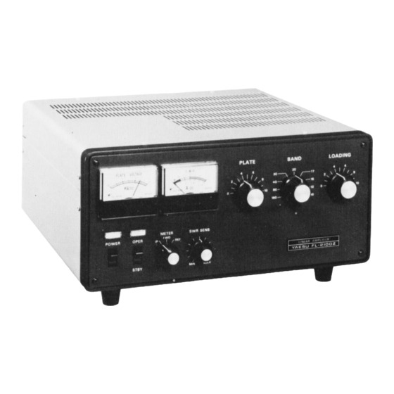
FRONT PANEL CONTROLS AND SWITCHES CD®® ® POWER PLATE This is the main power on/off switch for the This control adjusts the tuning. of the plate tank amplifier. capacitor. OPER/STBY ( 8) SWR/ AMMETER This switch applies bias to the final tubes during This meter displays either the feedline SWR or standby (STBY) operation, cutting them off. - Page 5 REAR APRON CONNECTIONS FUSE This UHF connector provides the R F output to the For AC 100/110/117 volts, use a 20 amp fuse. For AC 200/220/234 volts, use a 15 amp fuse. Do not antenna. use a fuse of the improper rating. (5) ALC The RF input from the transceiver should be This R CA jack is used for connection to the trans...
-
Page 6: Installation
DAMAGE cabinet. Do not place books, papers, or other CAUSED IMPROPER SUPPLY equipment on top of the FL-2100Z , and do not VOLTAGE OR USE OF AN IMPROPER obstruct the free flow of air from the fan exhaust FUSE. ports. - Page 7 FL-2100Z FT-101ZD RF OUT RF IN GND ALC RY ACC (PIN (INNER CONDUCTOR) !PIN (OUTER CONDUCTOR) ACC fPIN (INNER CONDU CTOR) \PIN '(OUTER CONDUC TOR) INTERCONNECTIONS For test purposes, the For normal operation plug may bejumpered using theFT-lOlZD relay, connect the plug as shown above.
-
Page 8: Operation
0.5 amperes. Approxi NECTED TO THE RF OUT JACK. mate settings of the FL-2100Z LOAD control f o r maximum output into a 50 ohm load are shown The exciter may be tuned up with the amplifier in Table l . - Page 9 CIRCUIT DESCRIPTION FL-2100Z uses two 572B/T l60 zero bias The bias level is set by When the antenna relay • triodes in a Class AB2 grounded grid configuration. is switched to the transmit condition, a timing RL301 circuit controls to keep the tubes biased to...
-
Page 10: Maintenance And Alignment
MAINTENANCE AND ALIGNMENT REMOVAL OF THE PA COMPARTMENT W A RNING SHIELD COVER LETHAL VOLTAGES ARE PRESENT WITHIN THE CABINET OF THIS EQUIPMENT. BEFORE Once the cabinet is removed, the shield cover for REMOVING THE CABINET OF THIS AMPLI the PA compartment may be removed by taking FIER, UNPLUG THE POWER CORD FROM THE off the screws of the shield cover. - Page 11 If this is impossible, shield cover and the cabinet be fore plugging the write to the Yaesu agent in your country, including AC cord into the AC supply outlet. Never apply as many details of the problem 1s possible. In AC power with the shield cover removed.
- Page 12 Do not exceed 10 seconds of key down time while of the exciter for a reading of 0.5 amps of plate current on the FL-2100Z IP meter. performing this adjustment. The use of a foot switch, or an assistant, is highly recommended.
- Page 13 MAIN CHASSIS TRIMMER CAPACITOR SOpF Parts No. ECV-1ZWS0x32 Symbol No. Description K91000016 VACUUM TUBE K91000006 TSN-1SOC30P 30pF Vl,2 G609000S S72B/Tl60 INDUCTOR VACUUM TUBE SOCKET 11020667 DA204UX VSl,2 P3090047 110206S9 SS000018 PLATE CAP HV-3001 11020661 L4,S(R6,9) 11020664 10020758 DIODE L00208SO G2010070 Germanium 1Sl007 11020064...
- Page 14 AC CORD CM COUPLER T7600001 2 wire, 2 prong plug L201 L0020301A T9000382 3 wire, 3 prong UL plug T9000680 3 wire, 3 prong Australian plug T9000584 3 wire, 2 prong EU plug BIAS CO NT. BOARD Symbol No. Parts No. Description PB-1903 F0001903...
- Page 15 YAESU 8003- Q...
Need help?
Do you have a question about the FL-2100Z and is the answer not in the manual?
Questions and answers