Advertisement
Quick Links
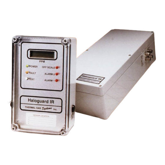
HALOGUARD
(OPTIONAL) FOUR or EIGHT POINT SCANNER
INSTRUCTION MANUAL
S E R IA L N O .
M O D E L N O .
T em p . R an ge
o
1 - = > 60
F
o
2 - = 40 - 60
F
o
3 - = < 40
F
G as T yp e
1 - R -1 1
2 - R -1 2
3 - R -2 2
4 - R -1 34a
5 -
6 -
7 - R -1 23
11285 Elkins Road Bldg. H-1
TM
IR MONITOR
M ou n t
O u tp uts
1 - W all
11 - 4 x 3 A R elays
12 - 0 - 5 V D C or
13 - 4 - 20m A
R an ge
1 - 0 - 1000 pp m
A - Aud ible A larm
B - U P S
E - Inlet/O utlet E xtension
L - Strobe Light
S - S canner
T - T W A Integration
Roswell, GA 30076
TEL: 770-667-3865
FAX: 770-667-3857
www.thermalgas.com
1
0 - 10 V D C
O ption s/A ccessories
Rev.2 1/26/98
Advertisement

Subscribe to Our Youtube Channel
Related Manuals for Thermal Gas Systems HALOGUARD Series


Summary of Contents for Thermal Gas Systems HALOGUARD Series
-
Page 1: Instruction Manual
HALOGUARD IR MONITOR (OPTIONAL) FOUR or EIGHT POINT SCANNER INSTRUCTION MANUAL S E R IA L N O . M O D E L N O . T em p . R an ge M ou n t O u tp uts 1 - = >... -
Page 2: Table Of Contents
IMPORTANT READ ENTIRE BOOKLET BEFORE INSTALLING OR OPERATING HALOGUARD IR MONITOR AND (OPTIONAL) SCANNER TABLE OF CONTENTS Page 1. Unpacking Instructions 2. Before Installation 3. Installation 4. Calibration 5. Testing 6. Trouble Shooting 7. Specifications FIGURES Page 1. Dimension Drawing 2. -
Page 3: Unpacking Instructions
UNPACKING INSTRUCTIONS Haloguard monitors are carefully packed, inspected and delivered to the carrier in good condition. If damage occurs in transit it is the responsibility of the carrier. Carefully inspect the unit upon receipt. Any damage should be reported to the carrier and an inspection requested. - Page 4 5. LED Indicators, Pushbuttons, LCD Displays, and Relays ® a. POWER LED- Green LED indicates Haloguard is receiving AC power. b. FAULT LED and Relay - Indicates malfunction. LCD indicates specific type of failure (See Figure 4). c. TEST Push-button - Energizes Alarm LED’s & relays. Depress button five (5) times to sequence through each alarm level.
- Page 5 ALARM Setup Jumpers ZERO SPAN LCD Brightness Adjustment Power LED Offscale LED ENTER DOWN Fault LED Alarm 2 LED Processor Test Button Alarm 1 LED Chip Reset Button Analog Trim Pot 0-5 or 0-10 VDC Scanner Connection VOLT RS-232 ANALOG Sensor Connection Trim...
- Page 6 Channels 1 - 8 (Optional Scanner Only) Flashing cursor means Auto Scan Mode (Opt. Scanner Only) Gas Type (R-11, R-12, R-123, R-134, etc.) Fault Messages - Caution - Chopper Failure - Discontinuity - Lamp Failure - Scan Discontinuity - Low Temp - Pump Failure - Scan Stop Concentration...
-
Page 7: Installation
INSTALLATION 1. Check power supply. (See Section “Before Installation 3a”) 2. Disconnect power before beginning. ® 3. Installation of Haloguard Controller and IR Sensor Module ® a. To mount Haloguard Controller 1. Remove Plastic cover. 2. Install No. 8 x 1” screw (minimum) wall fastener through cover screw holes. 3. - Page 8 e. Locate Setup jumpers on Figure 2 - Controller Upper Circuit Board. Select required settings from the following: FUNCTION Select run for normal operation Set Gas Type ALARM Alarm 1 and Alarm 2 Set Point Adjustment ZERO Factory Use Only SPAN Factory Use Only Factory Use Only...
- Page 9 ® Controller and IR Sensor Module (Extended Cable Procedure) 4. Installation of Haloguard Refer to FIGURE 2 - Controller Upper Circuit Board before proceeding. DO NOT CUT SUPPLIED CABLE Maximum Extension wire 1000 Feet. a. Controller is provided with 18” cable with DIN Connector and sensor is provided with 6-1/2’ cable. If cable extension is provided by customer, proceed as follows: We recommend 3 conductor 18 ga.
-
Page 10: Calibration
CALIBRATION Haloguard IR monitors are factory calibrated to the gas of interest; field recalibration is not required for operation in typical machine room environments during the first twelve months of operation unless drift exceeds more than 5ppm in a 30 day period. For those who wish to check the factory calibration an optional Digital Calibrator and Span Gas Kit is available. -
Page 11: Specifications
SPECIFICATIONS Technology: Photoacoustic Infrared Operating Conditions: IR Module F to +110 F Non-condensing Electrical Supply: 115-230 VAC, 50-60Hz Controller F to +120 F Non-condensing Output Signal: Std. 4 x 3A Dry Contact Relays Fault Diagnostics: Indicator Light or LCD Readout for (either NO or NC) fault diagnostics See Figure 5) Materials:... -
Page 12: Controller Upper Circuit Board
(OPTIONAL) STROBE LIGHT WARNING Analog output lines IR SENSOR MODULE ® ® ® ® HALOGUARD IR CONTROLLER must not be connected Upper Circuit Board to any kind of voltage or current source, See Chart for Connection serious damage will result +V S G Lower Circuit Board Green...
Need help?
Do you have a question about the HALOGUARD Series and is the answer not in the manual?
Questions and answers