Carrier 38HDR Installation Instructions Manual
Ducted condensing units
Hide thumbs
Also See for 38HDR:
- Owner's information manual (7 pages) ,
- Installation instructions manual (27 pages) ,
- Product data (43 pages)
Table of Contents
Advertisement
38HDR
Ducted Condensing Units
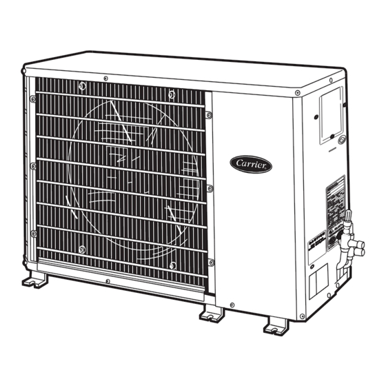
Fig. 1 --- 38HDR
NOTE: Read the entire instruction manual before starting the
installation.
TABLE OF CONTENTS
. . . . . . . . . . . . . . . . . . . . . . . . . . . . . . . .
. . . . . . . . . . . . . . . . . . . . . . . . . . . . . . . . . . . . . . .
. . . . . . . . . . . . . . . . . . . . . . . . . . . . . . . . . . . . . . . .
. . . . . . . . . . . . . . . . . . . . . . . . . . . . . . . . . .
. . . . . . . . . . . . . . . . . . . . . . . . . . . . .
Installation Instructions
PAGE
. . . . . . . . . . . . . . . . . . . . . . . .
. . . . . . . . . . . .
. . . . . . . . . . . . . . . . . . . . . .
. . . . .
. . . . . . . . . . . . . . . .
SAFETY CONSIDERATIONS
Improper installation, adjustment, alteration, service, maintenance,
or use can cause explosion, fire, electrical shock, or other
conditions which may cause death, personal injury, or property
damage. Consult a qualified installer, service agency, or your
distributor or branch for information or assistance. The qualified
installer or agency must use factory- -authorized kits or accessories
when modifying this product. Refer to the individual instructions
packaged with the kits or accessories when installing.
Follow all safety codes. Wear safety glasses, protective clothing,
and work gloves. Use quenching cloth for brazing operations.
Have fire extinguisher available. Read these instructions
thoroughly and follow all warnings or cautions included in
literature and attached to the unit. Consult local building codes and
National Electrical Code (NEC) for special requirements.
Recognize safety information. This is the safety- -alert symbol
A07532
When you see this symbol on the unit and in instructions or
manuals, be alert to the potential for personal injury. Understand
these signal words; DANGER, WARNING, and CAUTION. These
words are used with the safety- -alert symbol. DANGER identifies
the most serious hazards which will result in severe personal injury
or death. WARNING signifies hazards which could result in
personal injury or death. CAUTION is used to identify unsafe
practices which would result in minor personal injury or product
and property damage. NOTE is used to highlight suggestions
1
which will result in enhanced installation, reliability, or operation.
2 - - 9
!
2
2
4
7
10
10
14
14
WARNING
!
!
Advertisement
Table of Contents

Subscribe to Our Youtube Channel
Related Manuals for Carrier 38HDR


Summary of Contents for Carrier 38HDR
-
Page 1: Table Of Contents
National Electrical Code (NEC) for special requirements. Recognize safety information. This is the safety- -alert symbol A07532 Fig. 1 --- 38HDR When you see this symbol on the unit and in instructions or manuals, be alert to the potential for personal injury. Understand these signal words;... -
Page 2: Installation
Matching the Condensing Unit to an Indoor Unit The 38HDR018- -060 ducted condensing units can be matched to CAUTION corresponding indoor units. The 38HDR unit can be matched with under- -ceiling and residential fan coils and evaporator coils. Refer to separate indoor unit literature for more information. - Page 3 Fig. 2 --- 38HDR Unit Dimensions...
-
Page 4: Step 3 -Complete Refrigerant Piping Connec- Tions
Step 3 —COMPLETE REFRIGERANT PIPING CONNEC- Rigging TIONS CAUTION Outdoor units may be connected to indoor units using field- -supplied tubing of refrigerant grade and condition. See Table 1 for correct line sizes. Do not use less than 10 ft (3.05 m) of PERSONAL INJURY AND/OR... - Page 5 Filter Drier Make Piping Sweat Connections The filter drier must be replaced whenever the refrigeration system Remove plastic caps from liquid and suction service valves. Use is exposed to the atmosphere. refrigerant grade tubing. Service valves are closed from the factory and are ready for brazing.
- Page 6 Table 1—38HDR018- -060 Physical Data UNIT 38HDR NOMINAL CAPACITY Tons OPERATING WEIGHT lb (kg) 166 (75.30) 176 (79.83) 250 (113.4) 250 (113.4) 278 (126.10) 306 (138.80) REFRIGERANT TYPE Puronr (R --- 410A) METERING DEVICE CHARGE lb (kg)* 6.3 (2.86) 6.5 (2.95) 10.0 (4.54)
-
Page 7: Step 4 -Make Electrical Connections
Fig. 6. Unit must be grounded. Connections to Duct Free Fan Coil Units The 38HDR units are designed for easy match- -up to 40QA duct free fan coils. This unit provides 24 v power for the outdoor unit from the fan coil. - Page 8 Table 2—38HDR Electrical Data VOLTAGE 38HDR COMPRESSOR OUTDOOR FAN MOTOR FUSE/BKR RANGE* UNIT V ---PH ---Hz AMPS SIZE AMPS 208/230--- 1--- 60 48.0 0.80 0.125 0.09 12.1 208/230--- 1--- 60 12.8 58.3 0.80 0.125 0.09 16.8 208/230--- 1--- 60 14.1 73.0...
- Page 9 “C” on the low voltage board. 5. Use minimum 60° C wire for field power wiring. 6. Crankcase heater and thermostat used on selected models only. 38HDR OPERATION SEQUENCE CALL FOR COOLING: 1. Control voltage from transformer to thermostat (24 v).
-
Page 10: Start- -Up
Be sure that the field disconnect is closed. Set room thermostat below ambient temperature. Operate unit for 15 minutes, then check system refrigerant charge. See Refrigerant Charging section on page 12. 38HDR Unit Size, in. (mm) NOTE: When using in conjunction with 40QA fan coils, refer to 018,024 030,036... - Page 11 High- -Pressure Switch Refrigerant Charging The high- -pressure switch, located on discharge line, protects WARNING against high discharge pressures caused by such events as overcharge, condenser- -fan motor failure, system restriction, etc. It opens on pressure rise at about 650 ± 10 psig. If system pressures PERSONAL INJURY AND/OR EQUIPMENT go above this setting during abnormal conditions, the switch...
- Page 13 15 ft respectively. 4. If the measured liquid line temperature does not agree with For 38HDR units, the subcooling method is used to check and the required liquid line temperature, ADD refrigerant to adjust charge during the cooling season. Refer to Table 4 and the...
-
Page 14: Maintenance
A07402 Fig. 8 --- Troubleshooting the Cooling Cycle Catalog No: 38HDR ---5SI Copyright 2007 Carrier Corp. S 7310 W. Morris St. S Indianapolis, IN 46231 Printed in U.S.A. Edition Date: 06/07 Manufacturer reserves the right to change, at any time, specifications and designs without notice and without obligations.
Need help?
Do you have a question about the 38HDR and is the answer not in the manual?
Questions and answers