Carrier 38YKC Series Installation And Start-Up Instructions Manual
10 seer split system
Hide thumbs
Also See for 38YKC Series:
- Wiring diagrams (12 pages) ,
- Manual to operating & maintenance (6 pages)
Advertisement
Visit www.carrier.com
Installation and Start-Up Instructions
NOTE: Read the entire instruction manual before starting the
installation.
This symbol → indicates a change since the last issue.
SAFETY CONSIDERATIONS
Improper installation, adjustment, alteration, service, maintenance,
or use can cause explosion, fire, electrical shock, or other
conditions which may cause death, personal injury, or property
damage. Consult a qualified installer, service agency, or your
distributor or branch for information or assistance. The qualified
installer or agency must use factory-authorized kits or accessories
when modifying this product. Refer to the individual instructions
packaged with the kits or accessories when installing.
Follow all safety codes. Wear safety glasses, protective clothing,
and work gloves. Use quenching cloth for brazing operations.
Have fire extinguisher available. Read these instructions thor-
oughly and follow all warnings or cautions included in literature
and attached to the unit. Consult local building codes and National
Electrical Code (NEC) for special requirements.
Recognize safety information. This is the safety-alert symbol
When you see this symbol on the unit and in instructions or
manuals, be alert to the potential for personal injury.
Understand the signal words DANGER, WARNING, and CAU-
TION. These words are used with the safety-alert symbol. DAN-
GER identifies the most serious hazards which will result in severe
personal injury or death. WARNING signifies hazards which
could result in personal injury or death. CAUTION is used to
identify unsafe practices which would result in minor personal
injury or product and property damage.
Before installing, modifying, or servicing system, main elec-
trical disconnect switch must be in the OFF position. There
may be more than 1 disconnect switch. Lock out and tag
switch with a suitable warning label. Electrical shock can
cause personal injury or death.
→
INSTALLATION RECOMMENDATIONS
NOTE: In some cases noise in the living area has been traced to
gas pulsations from improper installation of equipment.
1. Locate unit away from windows, patios, decks, etc. where unit
operation sounds may disturb customer.
2. Ensure that vapor and liquid tube diameters are appropriate to
capacity of unit.
3. Run refrigerant tubes as directly as possible by avoiding
unnecessary turns and bends.
4. Leave some slack between structure and unit to absorb
vibration.
5. When passing refrigerant tubes through the wall, seal opening
with RTV or other pliable silicon-based caulk. (See Fig. 2.)
6. Avoid direct tubing contact with water pipes, duct work, floor
joists, wall studs, floors, and walls.
Manufacturer reserves the right to discontinue, or change at any time, specifications or designs without notice and without incurring obligations.
Book 1 4
PC 101
Tab 5a 5a
Catalog No. 563-718
Printed in U.S.A.
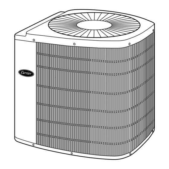
10 SEER Split System
Fig. 1—Model 38YKC
.
7. Do not suspend refrigerant tubing from joists and studs with a
rigid wire or strap which comes in direct contact with tubing.
(See Fig. 2.)
8. Ensure that tubing insulation is pliable and completely sur-
rounds vapor tube.
9. When necessary, use hanger straps which are 1 in. wide and
conform to shape of tubing insulation. (See Fig. 2.)
10. Isolate hanger straps from insulation by using metal sleeves
bent to conform to shape of insulation.
When outdoor unit is connected to factory-approved indoor unit,
outdoor unit contains system refrigerant charge for operation with
indoor unit of the same size when connected by 15 ft of
field-supplied or factory accessory tubing. For proper unit opera-
tion, check refrigerant charge using charging information located
on control box cover.
IMPORTANT: Maximum liquid-line size is 3/8-in. O.D. for all
residential applications including long line.
IMPORTANT: Always install a liquid-line filter drier. Refer to
Product Data Sheet for appropriate part number. Obtain filter drier
from service parts or your distributor or branch.
Step 1—Check Equipment and Job Site
UNPACK UNIT
Move to final location. Remove carton taking care not to damage
unit.
INSPECT EQUIPMENT
File claim with shipping company prior to installation if shipment
is damaged or incomplete. Locate unit rating plate on unit corner
panel. It contains information needed to properly install unit.
Check rating plate to be sure unit matches job specifications.
Form 38YKC-2SI
38YKC
Heat Pump
INSTALLATION
Pg 1
11-98
Replaces: 38YKC-1SI
A98519
Advertisement
Table of Contents

Subscribe to Our Youtube Channel
Related Manuals for Carrier 38YKC Series


Summary of Contents for Carrier 38YKC Series
-
Page 1: Heat Pump
Consult local building codes and National Electrical Code (NEC) for special requirements. A98519 Fig. 1—Model 38YKC Recognize safety information. This is the safety-alert symbol When you see this symbol on the unit and in instructions or 7. - Page 2 NOTE: Avoid contact between tubing and structure 3 /8 - IN. DIA TIEDOWN KNOCKOUTS IN BASEPAN (2) PLACES OUTDOOR WALL INDOOR WALL CAULK LIQUID TUBE VAPOR TUBE INSULATION THROUGH THE WALL JOIST ″ VIEW FROM TOP HANGER STRAP (AROUND VAPOR INSULATION TUBE ONLY) VAPOR TUBE...
-
Page 3: Refrigerant Tubing
indoor coil piston with piston shipped with outdoor unit. The piston shipped with outdoor unit is correct for any approved indoor To prevent damage to unit or service valves observe the coil combination. following: • Use a brazing shield. • Wrap service valves with wet cloth or use a heat sink Remove indoor coil piston if unit is to be installed on system material. -
Page 4: Connect Control Wiring
→ Table 2—Accessory Usage REQUIRED FOR REQUIRED FOR LOW-AMBIENT LONG-LINE ACCESSORY APPLICATIONS APPLICATIONS* (BELOW 55°F) (OVER 50 FT) Crankcase Heater Evaporator Freeze Thermostat Accumulator Compressor Start Assist Capacitor and Relay Low-Ambient Controller, MotorMaster® Control, Low-Ambient Pressure Switch Wind Baffle See Low-Ambient Instructions Support Feet Recommended Liquid-Line Solenoid Valve... - Page 5 IMPORTANT: When using outdoor thermostats, W 2 must be energized when requesting supplemental heat. CONNECTION A97536 A98629 Fig. 8—Typical 24-v Circuit Connections using Carrier Model HP Thermostat with Fan Coils and No Outdoor Thermostat, 1 Outdoor Thermostat, or 2 Outdoor Thermostats...
- Page 6 FA, FB, FC, OTHER FD, FF, FH HEAT FA, FB, FC, HP THERMOSTAT PUMP FAN COIL OTHER FD, FF, FH HEAT OUTDOOR HP THERMOSTAT PUMP FAN COIL THERMOSTAT 24 VAC HOT 24 VAC HOT 24 VAC COM 24 VAC COM HEAT STAGE 2 HEAT STAGE 2 COOL/HEAT...
- Page 7 Y1/W2. Refer to FK4 or 40FKA Installation Instructions. A97543 A98631 Fig. 10—Typical 24-v Circuit Connections using Carrier Model HP Thermostat with Smart Heat and No Outdoor Thermostat, 1 Outdoor Thermostat, or 2 Outdoor Thermostats and Carrier Model 2S Thermostat with FK4C/40FKA Fan Coil and Intelligent Staging...
- Page 8 FA, FB, FC, FH FA, FB, FC, FH OTHER HEAT OTHER FAN COIL HEAT FAN COIL HP THERMOSTAT SMART HEAT PUMP HP THERMOSTAT SMART HEAT PUMP 24 VAC HOT 24 VAC HOT 24 VAC COM 24 VAC COM COOL/HEAT COOL/HEAT STAGE 1 STAGE 1 INDOOR FAN...
-
Page 9: Wiring Diagram Notes
SENSOR SENSOR CONNECTION A97539 A97538 Fig. 12—Typical 24-v Circuit Connections using Carrier Model DF Thermostat with Single- or 2-Stage Furnace WIRING DIAGRAM NOTES: LEGEND 1. CARRIER THERMOSTAT WIRING DIAGRAMS ARE ONLY ACCU- 24-V FACTORY WIRING RATE FOR MODEL NUMBERS BEGINNING WITH TSTAT _ _ _ _ _ _ _. -
Page 10: Sequence Of Operation
Use furnace transformer, fan coil transformer, or accessory trans- SEQUENCE OF OPERATION former for control power, 24-v/40-va minimum. NOTE: Defrost control board may be equipped with 5-minute NOTE: Use of available 24-v accessories may exceed the mini- lockout timer which may be initiated upon any interruption of mum 40-va power requirement. - Page 11 6. To obtain required subcooling temperature at a specific liquid line pressure, add refrigerant if liquid line temperature is higher than indicated or reclaim refrigerant if temperature is lower. Allow a tolerance of ± 3°F. Table 4—Required Liquid-Line Temperature (°F) REQUIRED SUBCOOLING LIQUID TEMPERATURE...
-
Page 12: Care And Maintenance
25 ft - 15 ft = 10 ft X 0.6 oz/ft = 6 oz of additional charge areas, such as coastal applications. Copyright 1998 CARRIER Corp. • 7310 W. Morris St. • Indianapolis, IN 46231 38ykc2si Manufacturer reserves the right to discontinue, or change at any time, specifications or designs without notice and without incurring obligations.
Need help?
Do you have a question about the 38YKC Series and is the answer not in the manual?
Questions and answers