Table of Contents
Advertisement
Advertisement
Table of Contents

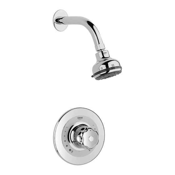
Summary of Contents for Grohe Grohsafe
- Page 1 950632.book : t95063.fm Seite 1 Mittwoch, Oktober 4, 2000 7:42 AM Grohsafe Concealed Pressure Balance Valve with Shower Kit 35 235 35 236 Installation Instructions and Operating Guide Please leave this document with the user after finishing installation! 95.063.231/ÄM 49 016/10.00...
- Page 2 kl950632.fm Seite 1 Montag, Oktober 2, 2000 8:25 AM Table Of Contents Installation Dimensions (mm) 35 235 35 235 35 236 Rosette Handshower Shower Rail Filter Shower Arm Filter Flexible Hose Headshower 35 235 Mixer Body and 35 236 Fitting Template Screws Wallplugs 35 236...
- Page 3 kl950632.fm Seite 2 Montag, Oktober 2, 2000 8:25 AM Spare Parts Spare Parts Spare Parts 35 235 35 236 10.1 10.2 10.2.1 12.2 12.1...
-
Page 4: Table Of Contents
Rough Installation ....7 Thank you for choosing a GROHE product. Preassemble Valve ....8 Please follow these instructions carefully Wall Plate Installation. -
Page 5: Technical Data
950632.book : i95063gb.fm Seite 6 Mittwoch, Oktober 4, 2000 7:42 AM Technical Data Functioning Principle Specification The Grohsafe pressure balance valve is a • Concealed single handle pressure safety mixer designed to compensate for balancing shower valve. fluctuations in the water supply pressures, which would otherwise affect the mixed •... -
Page 6: Installation
950632.book : i95063gb.fm Seite 7 Mittwoch, Oktober 4, 2000 7:42 AM Installation Rough Installation 2.Drill 6mm diameter holes and insert the The pressure balance shower mixing valve supplied wallplugs (A1), see Fig. [2]. can be installed in two different ways. The mixing outlet can be at the bottom for use with a handshower or at the top for use with a headshower. -
Page 7: Preassemble Valve
950632.book : i95063gb.fm Seite 8 Mittwoch, Oktober 4, 2000 7:42 AM Installation Preassemble Valve on the valve body slot into the apertures on the back plate, see Fig. [6]. 1.Remove the two screws (B1) from the 3.Screw backplate (D) to bracket (A) with fitting template (B), then remove the fixing screws (D1). - Page 8 950632.book : i95063gb.fm Seite 9 Mittwoch, Oktober 4, 2000 7:42 AM Installation 6.Slide the compression nut (C1), then the ring (C2), over the pipe. Insert the pipe ends into the openings of the inlet and outlet connectors of valve body. Then slide the rings (C2) and nuts (C1) into place and tighten the compression nuts (torque min.
- Page 9 950632.book : i95063gb.fm Seite 10 Mittwoch, Oktober 4, 2000 7:42 AM Installation Wall Plate Installation 1.Remove the two screws (B1) from the fitting template (B), then remove the template, see Fig. [10]. Additionally seal the top edge of the wall plate with silicone if it is fitted against a particularly rough surface (deep tile joints, highly textured tile).
-
Page 10: Bottom Outlet Installation
950632.book : i95063gb.fm Seite 11 Mittwoch, Oktober 4, 2000 7:42 AM Installation Bottom Outlet Installation 7.Pull the pressure balancing cartridge (O) out of the valve body. Do not damage the 1.Install the mixer with the outlet down. O-ring seals, see Fig. [16]. 2.Shut off hot and cold water supply! 3.Remove the two screws (B1) from the fitting template (B), then remove the... -
Page 11: Reversed Supplies Installation
950632.book : i95063gb.fm Seite 12 Mittwoch, Oktober 4, 2000 7:42 AM Installation Reversed Supplies Installation 6.Pull the existing pressure balancing cartridge (O) out of the valve body. Do not For reversed supplies installation, the damage the O-ring seals, see Fig. [19]. cartridge must be rotated 180°... -
Page 12: Maximum Hot Water Limit Setting
950632.book : i95063gb.fm Seite 13 Mittwoch, Oktober 4, 2000 7:42 AM Installation 4.Place the hot water limit stop (K) over the Maximum Hot Water Limit Setting splines on the intermediate handle with the On applications requiring limiting the valve limit stop resting against the wall plate stop opening from full hot position, the adjustable post, see Fig. -
Page 13: Maintenance
Be sure that the stop ring (N) is in the position. previously noted position. 4.Loosen screws (H1) and remove wall plate (H). 5.Loosen screw (G1) and pull off driver (G), Check, clean and if necessary replace parts. see Fig. [24]. Only genuine GROHE replacement parts must be used. -
Page 14: Care
Care We want to ensure that you get long-lasting your fitting dull and scratched. As the for- satisfaction and pleasure from your GROHE mulations of commercially available cleaning fitting. Therefore, please read the following agents frequently change, we cannot gua-... -
Page 15: Guarantee
Fax: 01 81 / 5 94 88 98 © 1999 Friedrich Grohe AG Friedrich Grohe Aktiengesellschaft · Hauptstraße 137 · 58675 Hemer Tel. 0 23 72 / 93-0 · Telex 827433 · Fax: 0 23 72 / 93 13 22...


Need help?
Do you have a question about the Grohsafe and is the answer not in the manual?
Questions and answers