Advertisement
Quick Links
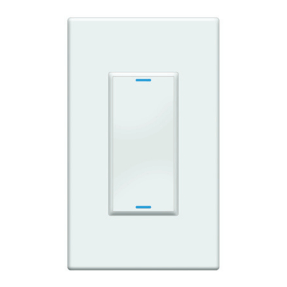
Wireless Switch
Installation Guide
Supported Models and Requirements
•
C4-SW1-Z Wireless Switch (802.15.4), White
Specifications and Supported Fixtures
This Control4
Wireless Switch operates independently or as part of a Control4® home
®
automation system to enable intelligent lighting control. It installs in a standard wall box
using typical wiring standards and communicates with other devices through a wireless
RF (radio frequency) connection. The specifications and supported fixtures are described
next.
Power:
120 VAC +/-10% 50/60 Hz
300 mW off
400 mW on
Supported Load Types
120 VAC 1000W Resistive
120 VAC 500W Tungsten
and Ratings:
120 VAC 1000W Electronic Low Voltage
120 VAC 1000W Magnetic Low Voltage
This device requires a neutral AC
connection.
Operating Temperature:
All load ratings are based on an ambient
temperature of 25 degrees Celsius.
Volume:
5.0 Cubic inches
Communications:
ZigBee, IEEE 802.15.4, 2.4 GHz,
15-channel, spread spectrum radio
Warnings and Considerations
WARNING! Install in accordance with all national and local electrical codes.
WARNING! Improper use or installation can cause SERIOUS INJURY,
DEATH or LOSS/DAMAGE OF PROPERTY.
WARNING! If you are unsure about any part of these instructions, consult a
qualified electrician.
WARNING! Use this device only with copper or copper clad wire. This prod-
uct has NOT been approved for use with Aluminum wiring.
IMPORTANT! Using this product in a manner other than outlined in this
document voids your warranty. Further, Control4 is NOT liable for any
damage incurred with the misuse of this product. See "Limited 2-Year
Warranty."
IMPORTANT! The range and performance of the wireless control system is
highly dependent on the following: (1) distance between devices; (2) layout of
the home; (3) walls separating devices; and (4) electrical equipment located
near devices.
Installation Instructions
1.
TURN OFF POWER by switching off the circuit breaker or removing
the fuse and test that power is off before wiring!
2.
Identify your wiring application (refer to the appropriate diagram on
the next page).
•
Single-Pole (with power source at wall box) - see Figure 1
•
3-Way (with power source at wall box) - see Figure 2
3.
Prepare the wires by removing pre-cut
insulation from the appropriate switch leads.
Wire insulation should be stripped back 5/8 of
an inch from the wire end (as shown).
4.
Connect the Switch wires to the wall box wires
using wire nuts according to the relevant
wiring diagram.
5.
Mount the Switch into the wall box by partially
securing the wall box screws attached to the
Switch. Ensure that the word "Top" on the
Switch frame is facing up. Bend the wires in a
zigzag pattern so that they easily fold into the
wall box.
WARNING! Ground the Wireless Switch in accordance with the National
Electric Code (NEC) requirements. Although the switch's aluminum yoke plate
and green ground wire are directly bonded together inside the Switch,
DO NOT rely solely upon the yoke plate's contact with a metal wall box for
adequate grounding. Use the Switch's ground wire to make a secure
connection to the safety ground of the electrical system.
IMPORTANT! Not grounding this product according to the preceding may
result in an installation less immune to damage caused by electrical
disturbances, such as lightning, and void the warranty.
6. If you are using the Control4 push-on (screw-less) wall plate that shipped with your
switch:
a. For a single-gang scenario, attach the black plastic sub-plate using the provided
sub-plate screws.
IMPORTANT! Tighten the screws until the back side of the metal yoke plate
is even with the wall surface, but no farther. Over-tightening can damage the
Switch and cause mechanical malfunction. Do NOT use a power screw driver
to install this device as this may lead to over-tightening.
b. If you are installing in a multi-gang scenario, only partially tighten the mounting
screws, leaving about 1/8 of an inch gap between the wall and the yoke plates
prior to attaching the black plastic sub-plate. This allows each device in a multi-
gang scenario to conform to the sub-plate, creating a single assembly. Secure
the multi-gang sub-plate to all devices using the provided sub-plate screws. Then
secure the assembly by tightening the wall box screws the remaining 1/8 of an
inch. Do not over-tighten any of the screws or you will mis-align the flat plane of
the multi-gang wall plate.
c. With the wall plate's removal slot facing down, push the wall plate onto
the switch's black plastic sub-plate.
7. If you are using Decora-style, screw-on the wall plate:
a.
Do not attach the Switch's black plastic sub-plate.
b.
Align the switch to the wall box and fasten it with screws.
c.
Fasten the wall plate to the Switch with screws.
8.
Turn ON power at the circuit breaker or replace the fuse from the fuse
box.
9.
Test the Switch to see if it's working properly. See "Operation and
Configuration" for specific instructions.
Advertisement

Related Manuals for Control 4 C4-SW1-Z


Summary of Contents for Control 4 C4-SW1-Z
-
Page 1: Installation Instructions
• Single-Pole (with power source at wall box) - see Figure 1 • 3-Way (with power source at wall box) - see Figure 2 Wireless Switch Prepare the wires by removing pre-cut insulation from the appropriate switch leads. Wire insulation should be stripped back 5/8 of Installation Guide an inch from the wire end (as shown). Supported Models and Requirements Connect the Switch wires to the wall box wires using wire nuts according to the relevant wiring diagram. • C4-SW1-Z Wireless Switch (802.15.4), White Specifications and Supported Fixtures This Control4 Wireless Switch operates independently or as part of a Control4® home ® automation system to enable intelligent lighting control. It installs in a standard wall box using typical wiring standards and communicates with other devices through a wireless RF (radio frequency) connection. The specifications and supported fixtures are described next. Power: 120 VAC +/-10% 50/60 Hz Mount the Switch into the wall box by partially 300 mW off securing the wall box screws attached to the 400 mW on Switch. Ensure that the word “Top” on the Switch frame is facing up. Bend the wires in a... -
Page 2: Troubleshooting
Sample Wiring Configurations Multi-Button Keypad Wires Wires in Wall Box 2 (from Wall Box 1) Single-Location Scenario—Power Source at Wall Box White (neutral) White (neutral) Green (ground) Green (ground) Note: This device will not function without a neutral AC connection. Black (traveler) Black (traveler) To wire the Switch for a Control4 single-location scenario in which the power is first routed to the wall box, connect together and cap with a wire nut the wires indicated in the Figure 2. Wiring: Two-Location Scenario following table and figure: Switch Wires Wires in the Wall Box From Power Source To Light Fixture White (neutral) White (neutral) -
Page 3: Regulatory Compliance
Regulatory Compliance FCC ID: R33C4SW1Z This device complies with Part 15 of the FCC Rules. Operation is subject to the following two conditions: (1) this device may not cause harmful interference, and (2) this device must accept any interference received, including interference that may cause undesired operation of this device. Son fonctionnement est soumis aux deux conditions suivantes: (1) cet appareil ne doit pas causer d’interférences nuisibles et (2) cet appareil doit accepter toute interférence reçue, y compris les interférences qui peuvent causer un mauvais fonctionnement du dispositif. This equipment has been tested and found to comply with the limits for a Class B digital device, pursuant to Part 15 of the FCC Rules. These limits are designed to provide reasonable protection against harmful interference in a residential installation. This equipment generates, uses, and can radiate radio frequency energy and, if not installed and used in accordance with the instructions, may cause harmful interference to radio communications. However, there is no guarantee that interference will not occur in a particular installation. If this equipment does cause harmful interference to radio or televi- sion reception, which can be determined by turning the equipment off and on, the user is encouraged to try to correct the interference by one or more of the following measures:• • Reorient or relocate the receiving antenna.• Increase the separation between the equipment and receiver. • Connect the equipment into an outlet on a circuit different from that to which the receiver is connected. • Consult the dealer or an experienced radio/TV technician for help. IMPORTANT! Any changes or modifications not expressly approved by the party responsible for compliance could void the user’s authority to operate this equipment. ETL Statement ETL Control Number: 3129831 This product has been tested by ETL and was found to comply with the Standard for Safety for Industrial Control Equipment: • UL/ANSI Standard 508 (Seventeenth Edition) • CSA Standard C22.2 No. 14-05 Industry Canada IC : 7848A-C4SW1Z This Class B digital apparatus complies with Canada ICES-003.